Asus DSBV-DX Bedienungsanleitung
Lesen Sie kostenlos die 📖 deutsche Bedienungsanleitung für Asus DSBV-DX (206 Seiten) in der Kategorie Server. Dieser Bedienungsanleitung war für 25 Personen hilfreich und wurde von 2 Benutzern mit durchschnittlich 4.5 Sternen bewertet
Seite 1/206

Motherboard
DSBV-DX
Series
DSBV-DX/SAS
DSBV-DX/C
DSBV-DX

ii
E3306
Second Edition V2
June 2007
Copyright © 2007 ASUSTeK COMPUTER INC. All Rights Reserved.
No part of this manual, including the products and software described in it, may be reproduced, transmitted,
transcribed, stored in a retrieval system, or translated into any language in any form or by any means,
except documentation kept by the purchaser for backup purposes, without the express written permission
of ASUSTeK COMPUTER INC. (“ASUS”).
Product warranty or service will not be extended if: (1) the product is repaired, modied or altered, unless
such repair, modication of alteration is authorized in writing by ASUS; or (2) the serial number of the
product is defaced or missing.
ASUS PROVIDES THIS MANUAL “AS IS” WITHOUT WARRANTY OF ANY KIND, EITHER EXPRESS
OR IMPLIED, INCLUDING BUT NOT LIMITED TO THE IMPLIED WARRANTIES OR CONDITIONS OF
MERCHANTABILITY OR FITNESS FOR A PARTICULAR PURPOSE. IN NO EVENT SHALL ASUS, ITS
DIRECTORS, OFFICERS, EMPLOYEES OR AGENTS BE LIABLE FOR ANY INDIRECT, SPECIAL,
INCIDENTAL, OR CONSEQUENTIAL DAMAGES (INCLUDING DAMAGES FOR LOSS OF PROFITS,
LOSS OF BUSINESS, LOSS OF USE OR DATA, INTERRUPTION OF BUSINESS AND THE LIKE),
EVEN IF ASUS HAS BEEN ADVISED OF THE POSSIBILITY OF SUCH DAMAGES ARISING FROM ANY
DEFECT OR ERROR IN THIS MANUAL OR PRODUCT.
SPECIFICATIONS AND INFORMATION CONTAINED IN THIS MANUAL ARE FURNISHED FOR
INFORMATIONAL USE ONLY, AND ARE SUBJECT TO CHANGE AT ANY TIME WITHOUT NOTICE, AND
SHOULD NOT BE CONSTRUED AS A COMMITMENT BY ASUS. ASUS ASSUMES NO RESPONSIBILITY
OR LIABILITY FOR ANY ERRORS OR INACCURACIES THAT MAY APPEAR IN THIS MANUAL,
INCLUDING THE PRODUCTS AND SOFTWARE DESCRIBED IN IT.
Products and corporate names appearing in this manual may or may not be registered trademarks or
copyrights of their respective companies, and are used only for identication or explanation and to the
owners’ benet, without intent to infringe.

iii
Contents
Notices ........................................................................................................ vii
Safety information .................................................................................... viii
About this guide ......................................................................................... ix
Typography .................................................................................................. x
DSBV-DX Series specications summary ................................................ xi
Chapter 1: Product introduction
1.1 Welcome! ...................................................................................... 1-1
1.2 Package contents .........................................................................1-1
1.3 Serial number label ......................................................................1-1
1.4 Special features ............................................................................1-2
1.4.1 Product highlights ...........................................................1-2
1.4.2 Innovative ASUS features ...............................................1-4
Chapter 2: Hardware information
2.1 Before you proceed ..................................................................... 2-1
2.2 Motherboard overview .................................................................2-2
2.2.1 Placement direction ........................................................2-2
2.2.2 Screw holes ....................................................................2-2
2.2.3 Support kits for the motherboard ....................................2-3
2.2.4 Motherboard layouts .......................................................2-6
2.2.5 Layout contents ...............................................................2-9
2.3 Central Processing Unit (CPU) .................................................2-11
2.3.1 Installing the CPU ..........................................................2-11
2.3.2 Installing the CPU heatsink and fan ..............................2-14
2.4 System memory .........................................................................2-16
2.4.1 Overview .......................................................................2-16
2.4.2 Memory congurations ..................................................2-16
2.4.3 Memory sparing technology ..........................................2-18
2.4.4 Installing a DIMM ..........................................................2-20
2.4.5 Removing a DIMM ........................................................2-20
2.4.6 Installing the MemCool FB-DIMM fan (opional) ............ 2-21
2.4.7 Uninstalling the optional MemCool FB-DIMM fan ........... 2-23
2.5 Expansion slots ..........................................................................2-24
2.5.1 Installing an expansion card .........................................2-24
2.5.2 Conguring an expansion card .....................................2-24
2.5.3 Interrupt assignments ...................................................2-25
2.5.4 PCI/PCI-X slots .............................................................2-26
2.5.5 PCI Express x8 slots (x8 and p3-x4 link) ...........................2-27
2.5.6 ZCR slot
(DSBV-DX/SAS model only) .......................... 2-27

iv
Contents
2.6 Jumpers ...................................................................................... 2-28
2.7 Connectors .................................................................................2-33
2.7.1 Rear panel connectors ..................................................2-33
2.8.2 Internal connectors .......................................................2-34
Chapter 3: Powering up
3.1 Starting up for the rst time ........................................................ 3-1
3.2 Turning off the computer .............................................................3-2
3.2.1 Using the OS shut down function ....................................3-2
3.2.2 Using the dual function power switch ..............................3-2
Chapter 4: BIOS setup
4.1 Managing and updating your BIOS ............................................ 4-1
4.1.1 Creating a bootable oppy disk .......................................4-1
4.1.2 Updating the BIOS using the Phoenix Phlash16 Utility ...4-2
4.1.3 ASUS CrashFree BIOS 2 utility ......................................4-3
4.1.4 ASUS Update utility ........................................................4-5
4.2 BIOS setup program .................................................................... 4-7
4.2.1 BIOS menu screen ..........................................................4-8
4.2.2 Menu bar .........................................................................4-8
4.2.3 Legend bar ......................................................................4-9
4.2.4 Menu items .....................................................................4-9
4.2.5 Sub-menu items ..............................................................4-9
4.2.6 Conguration elds .........................................................4-9
4.2.7 Pop-up window .............................................................4-10
4.2.8 General help .................................................................4-10
4.3 Main menu ..................................................................................4-11
4.3.1 System Date ..................................................................4-11
4.3.2 System Time ...................................................................411
4.3.3 Floppy A ........................................................................4-11
4.3.4 IDE Conguration ..........................................................4-12
4.3.5 IDE Primary Master/Slave; Secondary Master/Slave ...4-14
4.3.6 System Information .......................................................4-15
4.4 Advanced menu .........................................................................4-17
4.4.1 Advanced Processor Options .......................................4-17
4.4.2 Chipset Conguration ...................................................4-21
4.4.3 PCI Conguration ..........................................................4-23
4.4.4 ICH USB Control Sub-Menu .........................................4-24
4.4.5 Peripheral Devices Conguration .................................4-25
4.4.6 ACPI Conguration .......................................................4-27

v
Contents
4.4.7 Power On Conguration ................................................ 4-28
4.4.8 Hardware Monitor .........................................................4-29
4.5 Server menu ...............................................................................4-32
4.5.1 Console Redirection ......................................................4-32
4.5.2 DMI Event Logging .......................................................4-34
4.6 Security menu ............................................................................4-35
4.7 Boot menu ..................................................................................4-37
4.7.1 Boot Device Priority ......................................................4-37
4.7.2 Boot Features ...............................................................4-38
4.8 Exit menu ....................................................................................4-39
Chapter 5: nRAID conguratio
5.1 Setting up RAID ............................................................................ 5-1
5.1.1 RAID denitions ..............................................................5-1
5.1.2 Installing hard disk drives ................................................5-2
5.1.3 Setting the RAID item in BIOS ........................................5-2
5.1.4 RAID conguration utilities ..............................................5-2
5.2 LSI Logic Embedded SATA RAID Setup Utility ..........................5-3
5.2.1 Creating a RAID 0 or RAID 1 set ....................................5-4
5.2.2 Creating a RAID 10 set .................................................5-10
5.2.3 Adding or viewing a RAID conguration .......................5-14
5.2.4 Initializing the logical drives ..........................................5-17
5.2.5 Rebuilding failed drives .................................................5-22
5.2.6 Checking the drives for data consistency .....................5-24
5.2.7 Deleting a RAID conguration .......................................5-27
5.2.8 Selecting the boot drive from a RAID set ......................5-28
5.2.9 Enabling the WriteCache ..............................................5-29
5.3 Intel® Matrix Storage Manager Option ROM Utility ................. 5-30
5.3.1 Creating a RAID 0 set (Stripe) ......................................5-31
5.3.2 Creating a RAID 1 set (Mirror) ......................................5-33
5.3.3 Creating a RAID 10 set (Stripe + Mirror) .......................5-34
5.3.4 Creating a RAID 5 set (Parity) ......................................5-35
5.3.5 Deleting a RAID set ......................................................5-36
5.3.6 Resetting disks to Non-RAID ........................................5-37
5.3.7 Exiting the Intel® Matrix Storage Manager .................... 5-37
5.4 Global Array Manager ................................................................5-38
5.5 LSI Logic MPT Setup Utility
(DSBV-DX/SAS model only)
.5-39
5.5.1 Integrated Mirroring ....................................................... 5-39
5.5.2 Integrated Mirroring Enhanced .....................................5-43
5.5.3 Integrated Striping (IS) volume .....................................5-45

vi
Contents
5.5.4 Managing Arrays ........................................................... 5-48
5.5.5 Viewing SAS topology ................................................... 5-53
5.5.6 Global Properties ..........................................................5-55
Chapter 6: Driver installation
6.1 RAID driver installation ............................................................... 6-1
6.1.1 Creating a RAID driver disk ............................................6-1
6.1.2 Installing the RAID controller driver ................................6-4
6.2 Intel chipset software installation ............................................6-13
6.3 LAN driver installation ...............................................................6-16
6.3.1 Windows XP/2000/Server 2003 ....................................6-16
6.3.2 Red Hat/SuSE Linux .....................................................6-21
6.4 VGA driver installation............................................................... 6-22
6.4.1 Windows® 2000/Server 2003 ........................................ 6-22
6.5 Management applications and utilities installation ................6-24
6.5.1 Running the support CD ...............................................6-24
6.5.2 Drivers menu .................................................................6-24
6.5.3 Management Software menu ........................................6-25
6.5.4 Utilities menu ................................................................6-25
6.5.5 Contact information .......................................................6-25
Appendix: Reference information
A.1 DSBV-DX/SAS model block diagram ..........................................A-1
A.2 DSBV-DX/C model block diagram ...............................................A-2
A.3 DSBV-DX model block diagram ..................................................A-3

vii
Notices
Federal Communications Commission Statement
This device complies with Part 15 of the FCC Rules. Operation is subject to the
following two conditions:
•
This device may not cause harmful interference, and
•
This device must accept any interference received including interference that
may cause undesired operation.
This equipment has been tested and found to comply with the limits for a
Class B digital device, pursuant to Part 15 of the FCC Rules. These limits are
designed to provide reasonable protection against harmful interference in a
residential installation. This equipment generates, uses and can radiate radio
frequency energy and, if not installed and used in accordance with manufacturer’
s instructions, may cause harmful interference to radio communications. However,
there is no guarantee that interference will not occur in a particular installation. If
this equipment does cause harmful interference to radio or television reception,
which can be determined by turning the equipment off and on, the user is
encouraged to try to correct the interference by one or more of the following
measures:
•
Reorient or relocate the receiving antenna.
•
Increase the separation between the equipment and receiver.
•
Connect the equipment to an outlet on a circuit different from that to which the
receiver is connected.
•
Consult the dealer or an experienced radio/TV technician for help.
Canadian Department of Communications Statement
This digital apparatus does not exceed the Class B limits for radio noise emissions
from digital apparatus set out in the Radio Interference Regulations of the
Canadian Department of Communications.
This class B digital apparatus complies with Canadian ICES-003.
The use of shielded cables for connection of the monitor to the graphics card is
required to assure compliance with FCC regulations. Changes or modications
to this unit not expressly approved by the party responsible for compliance could
void the user’s authority to operate this equipment.

viii
Safety information
Electrical safety
•
To prevent electrical shock hazard, disconnect the power cable from the
electrical outlet before relocating the system.
•
When adding or removing devices to or from the system, ensure that the
power cables for the devices are unplugged before the signal cables are
connected. If possible, disconnect all power cables from the existing system
before you add a device.
•
Before connecting or removing signal cables from the motherboard, ensure
that all power cables are unplugged.
•
Seek professional assistance before using an adapter or extension cord.
These devices could interrupt the grounding circuit.
•
Make sure that your power supply is set to the correct voltage in your area.
If you are not sure about the voltage of the electrical outlet you are using,
contact your local power company.
•
If the power supply is broken, do not try to x it by yourself. Contact a
qualied service technician or your retailer.
Operation safety
•
Before installing the motherboard and adding devices on it, carefully read all
the manuals that came with the package.
•
Before using the product, make sure all cables are correctly connected and the
power cables are not damaged. If you detect any damage, contact your dealer
immediately.
•
To avoid short circuits, keep paper clips, screws, and staples away from
connectors, slots, sockets and circuitry.
•
Avoid dust, humidity, and temperature extremes. Do not place the product in
any area where it may become wet.
•
Place the product on a stable surface.
•
If you encounter technical problems with the product, contact a qualied
service technician or your retailer.

ix
About this guide
This user guide contains the information you need when installing and conguring
the motherboard.
How this guide is organized
This user guide contains the following parts:
• Chapter 1: Product introduction
This chapter describes the features of the motherboard and the new
technologies it supports.
• Chapter 2: Hardware information
This chapter lists the hardware setup procedures that you have to perform
when installing system components. It includes description of the switches,
jumpers, and connectors on the motherboard.
• Chapter 3: Powering up
This chapter describes the power up sequence and ways of shutting down
the system.
• Chapter 4: BIOS setup
This chapter tells how to change system settings through the BIOS Setup
menus. Detailed descriptions of the BIOS parameters are also provided.
• Chapter 5: RAID conguration
This chapter provides instructions for setting up, creating, and conguring
RAID sets using the available utilities.
• Chapter 6: Driver installation
This chapter provides instructions for installing the necessary drivers for
different system components.
• Appendix: Reference information
This appendix includes additional information that you may refer to when
conguring the motherboard.
Where to nd more information
Refer to the following sources for additional information and for product and
software updates.
1. ASUS websites
The ASUS website provides updated information on ASUS hardware and
software products. Refer to the ASUS contact information.
2. Optional documentation
Your product package may include optional documentation, such as warranty
yers, that may have been added by your dealer. These documents are not
part of the standard package.

x
Conventions used in this guide
To make sure that you perform certain tasks properly, take note of the following
symbols used throughout this manual.
Typography
Bold text Indicates a menu or an item to select.
Italics Used to emphasize a word or a phrase.
<Key> Keys enclosed in the less-than and greater-
than sign means that you must press the
enclosed key.
Example: <Enter> means that you must press
the Enter or Return key.
<Key1+Key2+Key3> If you must press two or more keys
simultaneously, the key names are linked with
a plus sign (+).
Example: <Ctrl+Alt+D>
Command Means that you must type the command
exactly as shown, then supply the required
item or value enclosed in brackets.
Example: At the DOS prompt, type the
command line: format A:/S
DANGER/WARNING: Information to prevent injury to yourself
when trying to complete a task.
CAUTION: Information to prevent damage to the components
when trying to complete a task.
NOTE: Tips and additional information to help you complete a
task.
IMPORTANT: Instructions that you MUST follow to complete a
task.

xi
DSBV-DX Series specications summary
(continued on the next page)
CPU Dual LGA771 sockets for Intel® Xeon™ Dual Core
processors 5000/5100 sequence (Dempsy/Woodcrest)
and Quad Core processor 5300 sequence (Clovertown)
Supports Intel® Extended Memory 64Technology (EM64T)
Supports Intel® Hyper-Threading Technology
Chipset
MCH: Intel® 5000V (Blackford-VS)
ICH:
Intel
® 6321ESB (ESB2)
System Bus 1333/1066/667 MHz
Memory Dual-channel memory architecture
6 x 240-pin FB-DIMM sockets support registered ECC
fully buffered DDR2-533/DDR2-667 memory modules
with Advanced Memory Buffer (AMB chip)
Supports 256 MB up to 24 GB system memory
Supports memory sparing technology.
Expansion Slots DSBV-DX
1 x PCI Express™ p11-x8 slot (x8 link)
1 x PCI Express™ p11-x8 slot (x4 link)
2 x PCI-X 133/100 MHz/64bit/3.3V slot
1 x PCI 33 MHz/32-bit/5V slot
DSBV-DX/C
1 x PCI Express™ p11-x8 slot (x8 link)
1 x PCI Express™ p11-x8 slot (x4 link)
2 x PCI-X 133/100 MHz/64bit/3.3V slot
1 x PCI 33 MHz/32-bit/5V slot
DSBV-DX/SAS
1 x PCI Express™ p11-x8 slot (x8 link)
1 x PCI Express™ p11-x8 slot (x4 link)
1 x PCI 33 MHz/32-bit/5V slot
1 x PCI-X 133/100 MHz/64bit/3.3V slot
1 x PCI-X 133/100 MHz/64bit/3.3V slot for optional Zero
Channel RAID (ZCR) card
(colored green)
Storage Intel ®
6321ESB supports:
- 2 x Ultra DMA 100/66/33 devices
- 6 x SATA II (3.0 Gb/s)
- Intel® Matrix Storage with RAID 0, RAID 1, RAID
0+1, and RAID 5 (S/W) conguration
- LSI MegaRAID controller with RAID 0, RAID 1, and
RAID 0+1 conguration
(DSBV-DX only)
(DSBV-DX/SAS model only)
LSI1068 PCI-X SAS controller supports:
- 8 x Serial Attached SCSI (SAS) channels
(8 devices) with RAID 0, RAID 1, and RAID 1E
conguration
- Zero-Channel RAID
(optional)

xii
DSBV-DX Series specications summary
LAN Intel® 82563EB (ESB2E/Gilgal) Network Connection
(Dual-port)
- Supports Intel I/O Acceleration Technology (IOAT)
- Supports 10/100/1000 BASE-T
Discrete graphics XGI Volari Z7 PCI display controller with 32MB of Video
memory
USB Intel® 6321ESB supports:
- 4 USB 2.0/1.1 ports (2 on the rear panel, 1 connector at
mid-board for 2 additional ports)
BIOS features PHOENIX BIOS, 8 Mb FWH, Green, PnP, DMI2.0a,
ACPI 2.0a, SMBIOS 2.3, WfM2.0
Rear panel 1 x PS/2 keyboard port (purple)
1 x PS/2 mouse port (green)
2 x USB 2.0 ports
1 x Serial port
1 x VGA port
2 x LAN (RJ-45) ports
Internal connectors 1 x Floppy disk drive connector
1 x IDE connector
6 x Serial ATA connectors
1 x Hard disk activity LED connector
1 x USB connector
1 x Serial port connector (10-1 pin COM2)
1 x Power supply SMBus connector
1 x Serial General Purpose Input/Output connector for LSI
MegaRAID SATA LED (6-1 pin SGPIO1)
1 x Parallel port connector
SSI power connectors (24-pin and 8-pin)
CPU (x2), rear (x2), front (x4), and FB DIMM (x1) fan
connectors
System panel connector (20-pin PANEL1)
Auxiliary panel connector (20-pin AUX_PANEL1)
(DSBV-DX/SAS model only)
1 x SAS LSI1068 port LED connector (18-1 pin SASLED1)
8 x SAS connectors support 8 devices (blue)
1 x Serial General Purpose Input/Output connector for LSI
SAS1068 controller (8-pin SGPIO2)
Power requirement SSI power supply (with 24-pin/8-pin 12V plugs)
for LGA771-socket Intel® Xeon Dual Core processors
(Bensley platform)
(continued on the next page)

xiii
*Specications are subject to change without notice.
DSBV-DX Series specications summary
Form factor SSI CEB 1.1 form factor: 12 in x 10.5 in (30.5 cm x 26.67
cm)
Support CD contents Device drivers
ASUS Update Utility
ASUS Server Web-based Management (ASWM)
Anti-virus software
Adobe Acrobat Reader
ASUS Screen Saver
ASUS Flash Utility under DOS

xiv

1
Product
introduction
This chapter describes the motherboard
features and the new technologies it supports.

ASUS DSBV-DX Series
Chapter summary
1
1.1 Welcome! ...................................................................................... 1-1
1.2 Package contents .........................................................................1-1
1.3 Serial number label ......................................................................1-1
1.4 Special features ............................................................................1-2

ASUS DSBV-DX Series 1-1
1.1 Welcome!
Thank you for buying an ASUS® DSBV-DX series motherboard!
The motherboard delivers a host of new features and latest technologies, making it
another standout in the long line of ASUS quality motherboards!
Before you start installing the motherboard, and hardware devices on it, check the
items in your package with the list below.
1.2 Package contents
Check your motherboard package for the following items.
If any of the above items is damaged or missing, contact your retailer.
DSBV-DX DSBV-DX/C DSBV-DX/SAS
Cables
SATA signal cables 6 6 6
SATA power cable (dual plug) 3 3 3
4 ports SATA to SAS cable -- -- 2
80-pin IDE + Floppy 2-in-1 cable 1 1 1
Accessories I/O shield 1 1 1
CEK spring 2 2 2
Application CDs Support CD 1 1 1
Documentation User Guide 1 1 1
Optional Pack MemCool FB-DIMM fan kit
Anti-virus software
1.3 Serial number label
Before requesting support from the ASUS Technical Support team, you must take
note of the motherboard's serial number containing 12 characters
xxM0Axxxxxxx
shown as the gure below. With the correct serial number of the product, ASUS
Technical Support team members can then offer a quicker and satisfying solution
to your problems.
xxM0Axxxxxxx
DSBV-DX Made
in
China
合格

1-2 Chapter 1: Product introduction
1.4 Special features
1.4.1 Product highlights
Latest processor technology
The motherboard comes with two LGA-771 sockets that support Dual-Core and
Quad-Core Intel® Xeon™ processors with 1333/1066/667 MHz Front Side Bus
(FSB). Dual-core processors contain two physical CPU cores to meet demands
for more powerful processing. Intel® Xeon™ processors incorporate the Intel®
Hyper-Threading Technology and Extended Memory 64-bit Technology (EM64T).
The EM64T enables the support for 64-bit operation system, such as 64-bit
Windows® and Linux. See page 2-11 for details.
Intel®
5000V
and Intel® 6321ESB chipset
The Intel®
5000V
Memory Controller Hub (MCH) and the Intel® 6321ESB provide
the vital interfaces for the motherboard.
The MCH provides the processor, dual-channel FB-DIMM memory support, and
PCI Express interfaces. The Intel
® 6321ESB is a new generation server class I/O
controller hub that provides the interface for PCI 2.3, PCI Express, and PCIX.
Intel® EM64T
The motherboard supports Intel® processors with the Intel® EM64T (Extended
Memory 64 Technology). The Intel
® EM64T feature allows your computer to run on
64-bit operating systems and access larger amounts of system memory for faster
and more efcient computing.
Enhanced Intel SpeedStep® Technology (EIST)
The Enhanced Intel SpeedStep® Technology (EIST) intelligently manages the
CPU resources by automatically adjusting the CPU voltage and core frequency
depending on the CPU loading and system speed or power requirement.
FB-DIMM memory support
This motherboard supports fully buffered DIMMs (FB-DIMMs), the latest memory
solution that extends memory capacity and provide high-speed, high-density
system memory peformance. FB-DIMMs use Advanced Memory Buffer (AMB)
chips that transmit signals between the memory modules and controllers with
improved signal integrity and reduced errors. See page 2-16 for details.

ASUS DSBV-DX Series 1-3
PCI Express™ interface
The motherboard fully supports PCI Express, the latest I/O interconnect technology
that speeds up the PCI bus. PCI Express features point-to-point serial
interconnections between devices and allows higher clockspeeds by carrying data
in packets. This high speed interface is software compatible with existing PCI or
PCI-X specications. See page 2-27 for details.
Serial Attached SCSI (SAS) technology support
(DSBV-DX/SAS model only)
SAS is the latest storage interface for enterprise-class storage devices. Building
on and improving the parallel SCSI foundation, SAS is the new industry standard
that includes Serial ATA interoperability, and is projected to be the succesor of the
Ultra320 SCSI technology. See page 2-36 for the location of the SAS connectors.
Zero-Channel RAID (ZCR) solution
(DSBV-DX/SAS model only)
The motherboard comes with a ZCR socket for an optional Zero-Channel RAID
card, allowing RAID 0 (striping), RAID 1 (mirroring), RAID 0+1, and RAID 5
congurations. The ZCR capability provides a cost-effective high-performance and
added reliability.
82563 LAN solution
The motherboard comes with a dual-port 82563EB network connection to provide a
total solution for your networking needs. See page 2-33 for the location of the LAN
ports. See section 2.6 Jumpers for details on Gigabit LAN settings.
Serial ATA II technology
The motherboard supports the Serial ATA II 3 Gb/s technology through 6321ESB
Serial ATA interfaces. The Serial ATA II specication provides twice the bandwidth
of the current Serial ATA products with a host of new features, including Native
Command Queuing (NCQ), Power Management (PM) Implementation Algorithm,
and Hot Swap. Serial ATA allows thinner, more exible cables with lower pin count
and reduced voltage requirements. See page 2-35 for details.
USB 2.0 technology
The motherboard implements the Universal Serial Bus (USB) 2.0 specication,
dramatically increasing the connection speed from the 12 Mbps bandwidth on USB
1.1 to a fast 480 Mbps on USB 2.0. USB 2.0 is backward compatible with USB 1.1.
See pages 2-33 for details.
1-4 Chapter 1: Product introduction
Temperature, fan, and voltage monitoring
The CPU temperature is monitored by the W83793G chip to prevent overheating
and damage. The system fan rotations per minute (RPM) is monitored for timely
failure detection. The chip monitors the voltage levels to ensure stable supply of
current for critical components. See page 4-29 for details.
Intel® IOAT
Intel® I/O Acceleration Technology (IOAT) is an integrated server platform I/O
solution that addresses all segments of the server I/O bottleneck problem using
TCP/IP without requiring any modication of existing or future applications.
Intel® IOAT is a system-wide solution that increases CPU efciency and delivers
data to/from applications faster than current server platforms.
1.4.2 Innovative ASUS features
CrashFree BIOS 2
This feature allows you to restore the original BIOS data from the support CD in
case when the BIOS codes and data are corrupted. This protection eliminates the
need to buy a replacement ROM chip. See page 4-3 for details.
ASUS Smart Fan technology
The ASUS Smart Fan technology smartly adjusts the fan speeds according to the
system loading to ensure quiet, cool, and efcient operation. See page 4-31 for
details.
ASUS MemCool FB-DIMM Fan Kit (optional)
With this optional fan kit, the platform gets optimal performance and the best
possible FB-DIMM thermal environment.

2
Hardware
information
This chapter lists the hardware setup
procedures that you have to perform
when installing system components. It
includes description of the jumpers and
connectors on the motherboard.

ASUS DSBV-DX Series
Chapter summary
2
2.1 Before you proceed ..................................................................... 2-1
2.2 Motherboard overview .................................................................2-2
2.3 Central Processing Unit (CPU) .................................................2-11
2.4 System memory .........................................................................2-16
2.5 Expansion slots ..........................................................................2-24
2.6 Jumpers ......................................................................................2-28
2.7 Connectors .................................................................................2-33

ASUS DSBV-DX Series 2-1
2.1 Before you proceed
Take note of the following precautions before you install motherboard components or change
any motherboard settings.
• Unplug the power cord from the wall socket before touching any
component.
• Use a grounded wrist strap or touch a safely grounded object or a metal
object, such as the power supply case, before handling components to
avoid damaging them due to static electricity.
• Hold components by the edges to avoid touching the ICs on them.
• Whenever you uninstall any component, place it on a grounded antistatic
pad or in the bag that came with the component.
• Before you install or remove any component, ensure that the power supply
is switched off or the power cord is detached from the power supply. Failure
to do so may cause severe damage to the motherboard, peripherals, and/or
components.
DSBV-DX
DSBV-DX Series Onboard LED
Blinks OFF
LED1
Normal Abnormal
ON OFF
SB_PWR1
Standby
Power
Powered
Off
(green)
(green)
Onboard LED
1. Standby Power LED
The motherboard comes with a standby power LED. The green LED lights up
to indicate that the system is ON, in sleep mode, or in soft-off mode. This is a
reminder that you should shut down the system and unplug the power cable
before removing or plugging in any motherboard component. The illustration
below shows the location of the onboard LED
2. SAS LED (for DSBV-DX/SAS only)
The green heartbeat LED blinks per second to indicate that the LSI 1068
chipset is working normally.
2-2 Chapter 2: Hardware information
DSBV-DX
2.2 Motherboard overview
Before you install the motherboard, study the conguration of your chassis to
ensure that the motherboard ts into it.
To optimize the motherboard features, we highly recommend that you install it in an
SSI CEB 1.1 compliant chassis.
2.2.1 Placement direction
When installing the motherboard, make sure that you place it into the chassis in the
correct orientation. The edge with external ports goes to the rear part of the chassis
as indicated in the image below.
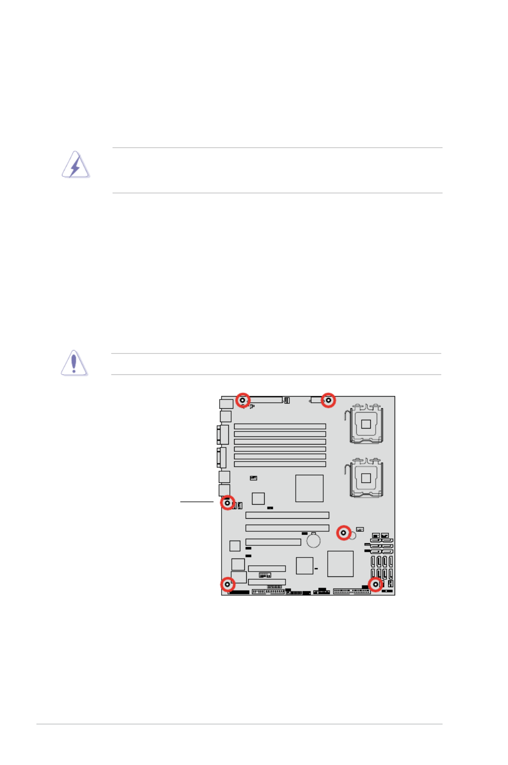
2.2.2 Screw holes
Place six (6) screws into the holes indicated by circles to secure the motherboard
to the chassis.
DO NOT overtighten the screws! Doing so can damage the motherboard.
Make sure to unplug the chassis power cord before installing or removing
the motherboard. Failure to do so can cause you physical injury and damage
motherboard components!
Place this side towards
the rear of the chassis

ASUS DSBV-DX Series 2-3
2.2.3 Support kits for the motherboard
For additional protection from motherboard breakage due to the weight of the CPU
heatsinks, your motherboard package comes with CEK springs that you can use as
weight support. Install the CEK springs before installing the motherboard.
Hook
Each CEK spring has four hooks to match the
designated holes around the CPU area.
If your chassis is SSI CEB 1.1 compliant, we recommend that you use the CEK
springs; otherwise, use the support plates kit.
To install the CEK spring:
1. Locate the CPU heatsink holes on
the motherboard.
2. Position the CEK spring underneath the motherboard, then match the CEK
spring hooks to the CPU1 heatsink holes.
Heatsink hole
Socket for CPU2
Socket for CPU1

2-4 Chapter 2: Hardware information
4. Press the lower spring clips inward,
then insert to the lower CPU
heatsink holes until they snap in
place.
5. If you installed a second CPU,
repeat steps 2 to 4 to install the
CEK spring to the CPU2 heatsink
holes.
The CEK springs appear as shown
when installed.
CEK spring screw hole
3. Press the upper spring hooks
inward, then insert to the upper
CPU heatsink holes until they snap
in place.

ASUS DSBV-DX Series 2-5
6. Before installing the motherboard
into the chassis, locate the standoffs
that should match the eight (8) CEK
spring screw holes.
8. Secure the motherboard with six (6) screws. Refer to section 2.2.2 Screw
holes for illustration.
Make sure that the standoffs perfectly match the CEK spring screw holes;
otherwise, you can not install the CPU heatsinks properly.
Standoffs for CPU1
Standoffs for CPU2
7. Install the motherboard with the
external I/O ports toward the
chassis rear panel. The CPU
sockets should be right on top of
their respective standoffs.
Socket for CPU2 Socket for CPU1
2-6 Chapter 2: Hardware information
2.2.4 Motherboard layouts
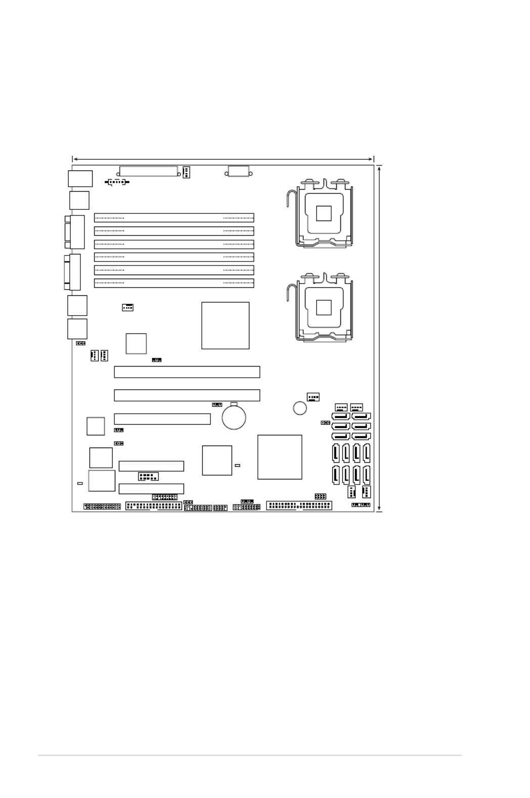
DSBV-DX/SAS model
8Mb
FWH
ATXPWR1
FLOPPY1
Z7
BUZZER1
COM2
Super
I/O
CR2032 3V
Lithium Cell
CMOS Power
PANEL1
PS/2
T: Mouse
B: Keyboard
USB12
ATX12V1
CPU_FAN1
Intel
®
6321ESB
PSUSMB1
AUX_PANEL1
HDLED1
USB34
LAN_BW1
LPT1
DSBV-DX/SAS
Intel
®
5000V
PCIE4
DIMM_00 (64/72 bit, 240-pin module)
26.7cm (10.5in)
30.5cm (12in)
COM1
VGA1
PCIX1
PCI3
REAR_FAN2
PRI_IDE1
FRNT_FAN2
SGPIO1
RECOVERY1
VGA_EN1
LAN_EN1
RJ-45
(LAN2)
DIMM_01 (64/72 bit, 240-pin module)
DIMM_02 (64/72 bit, 240-pin module)
DIMM_10 (64/72 bit, 240-pin module)
DIMM_11 (64/72 bit, 240-pin module)
DIMM_12 (64/72 bit, 240-pin module)
CPU1
CPU2
FRNT_FAN1
FRNT_FAN4
CPU_FAN2
REAR_FAN1
CLRTC1
FAN_SEL1
SAS1
SAS2
SAS3
SAS4
Intel
®
82563EB
LED1
SB_PWR1
PCIX2
PCIE5
RJ-45
(LAN1)
SASLED1 SAS_EN1
SATA4
SATA5
SATA6
SAS5
SAS6
SAS7
SAS8
FRNT_FAN3
SATA1
SATA2
SATA3
FBD_FAN1
LSI1068
SGPIO2

ASUS DSBV-DX Series 2-7
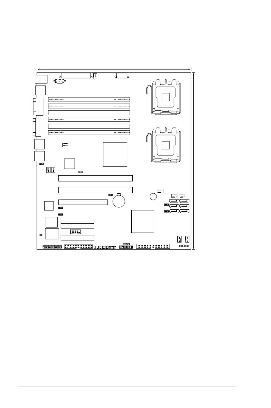
DSBV-DX/C model
8Mb
FWH
ATXPWR1
FLOPPY1
Z7
BUZZER1
COM2
Super
I/O
CR2032 3V
Lithium Cell
CMOS Power
PANEL1
PS/2
T: Mouse
B: Keyboard
USB12
ATX12V1
CPU_FAN1
Intel
®
6321ESB
PSUSMB1
AUX_PANEL1
HDLED1
USB34
LAN_BW1
LPT1
DSBV-DX/C
Intel
®
5000V
PCIE4
DIMM_00 (64/72 bit, 240-pin module)
26.7cm (10.5in)
30.5cm (12in)
COM1
VGA1
PCIX1
PCI3
REAR_FAN2
PRI_IDE1
FRNT_FAN2
SGPIO1
RECOVERY1
VGA_EN1
LAN_EN1
RJ-45
(LAN2)
DIMM_01 (64/72 bit, 240-pin module)
DIMM_02 (64/72 bit, 240-pin module)
DIMM_10 (64/72 bit, 240-pin module)
DIMM_11 (64/72 bit, 240-pin module)
DIMM_12 (64/72 bit, 240-pin module)
CPU1
CPU2
FRNT_FAN1
FRNT_FAN4
CPU_FAN2
REAR_FAN1
CLRTC1
Intel
®
82563EB
SB_PWR1
PCIX2
PCIE5
RJ-45
(LAN1)
SATA4
SATA5
SATA6
FRNT_FAN3
SATA1
SATA2
SATA3
FBD_FAN1
FAN_SEL1
2-8 Chapter 2: Hardware information
DSBV-DX model
8Mb
FWH
ATXPWR1
FLOPPY1
Z7
BUZZER1
COM2
Super
I/O
CR2032 3V
Lithium Cell
CMOS Power
PANEL1
PS/2
T: Mouse
B: Keyboard
USB12
ATX12V1
CPU_FAN1
Intel
®
6321ESB
PSUSMB1
AUX_PANEL1
HDLED1
USB34
LAN_BW1
LPT1
DSBV-DX
Intel
®
5000V
PCIE4
DIMM_00 (64/72 bit, 240-pin module)
26.7cm (10.5in)
30.5cm (12in)
COM1
VGA1
PCIX1
PCI3
REAR_FAN2
PRI_IDE1
FRNT_FAN2
SGPIO1
RECOVERY1
VGA_EN1
LAN_EN1
RJ-45
(LAN2)
DIMM_01 (64/72 bit, 240-pin module)
DIMM_02 (64/72 bit, 240-pin module)
DIMM_10 (64/72 bit, 240-pin module)
DIMM_11 (64/72 bit, 240-pin module)
DIMM_12 (64/72 bit, 240-pin module)
CPU1
CPU2
FRNT_FAN1
FRNT_FAN4
CPU_FAN2
REAR_FAN1
CLRTC1
Intel
®
82563EB
SB_PWR1
PCIX2
PCIE5
RJ-45
(LAN1)
SATA4
SATA5
SATA6
FRNT_FAN3
SATA1
SATA2
SATA3
FBD_FAN1
FAN_SEL1
RAID_SEL1

ASUS DSBV-DX Series 2-9
2.2.5 Layout contents
Slots/Soocket Page
1. CPU sockets 2-11
2. FB-DIMM sockets 2-16
3. PCI/PCI-X slots 2-26
4. PCI Express x 8 slots 2-27
6. ZCR slot (DSBV-DX/SAS model only) 2-27
Jumpers Page
1. Clear RTC RAM (CLRTC) 2-28
2. LAN bandwidth setting (3-pin LAN_BW1) 2-29
3. VGA controller setting (3-pin VGA_EN1) 2-29
4. LAN controller setting (3-pin LAN_EN1) 2-30
5. Fan control setting (3-pin FAN_SEL1) 2-30
6. Intel® 6321ESB SATA port S/W RAID setting (3-pin RAID_SEL1)
(DSBV-DXmodels only)
2-31
7. Onboard storage setting (3-pin SAS_EN1)
(DSBV-DX/SAS model only)
2-31
8. Force BIOS recovery setting (3-pin RECOVERY1) 2-32
Rear panel connectors Page
1. PS/2 mouse port (green) 2-33
2. PS/2 keyboard port (purple) 2-33
3. USB 2.0 ports 1 and 2 2-33
4. Serial (COM1) port 2-33
5. Video Graphics Adapter port 2-33
6. LAN (RJ-45) ports 2-33

2-10 Chapter 2: Hardware information
Internal connectors Page
1. Floppy disk drive connector (34-1 pin FLOPPY1) 2-34
2. IDE connector (40-1 pin PRI_IDE1) 2-34
3. Serial ATA connectors
(7-pin SATA1, SATA2, SATA3, SATA4, SATA5, SATA6 ) 2-35
4. Hard disk activity LED connector (4-pin HDLED1) 2-35
5. SAS connectors
(DSBV-DX/SAS model only)
2-36
6. SAS LSI1068 ports LED connector (18-1 pin SASLED1)
(DSBV-DX/SAS model only)
2-37
7. Serial General Purpose Input/Output connector
(6-1 pin SGPIO1) 2-37
8. USB connectors (10-1 pin USB34) 2-38
9. Serial port connectors (10-1 pin COM2) 2-38
10. CPU and system fan connectors (4-pin CPU_FAN1/2,
REAR_FAN1/2, FRNT_FAN1/2/3/4, FBD_FAN1) 2-39
11. Power supply SMBus connector (5-pin PSUSMB1) 2-39
12. SSI power connectors
(24-pin ATXPWR1, 8-pin ATX12V1) 2-40
13. Parallel port connector (26-1 pin LPT1) 2-41
14. Serial General Purpose Input/Output connector
(2x4 pin SGPIO2)
(DSBV-DX/SAS model only)
2-41
15. System panel connector (20-1 pin PANEL1) 2-42
16. Auxiliary panel connector (20-pin AUX_PANEL1) 2-43
ASUS DSBV-DX Series 2-11
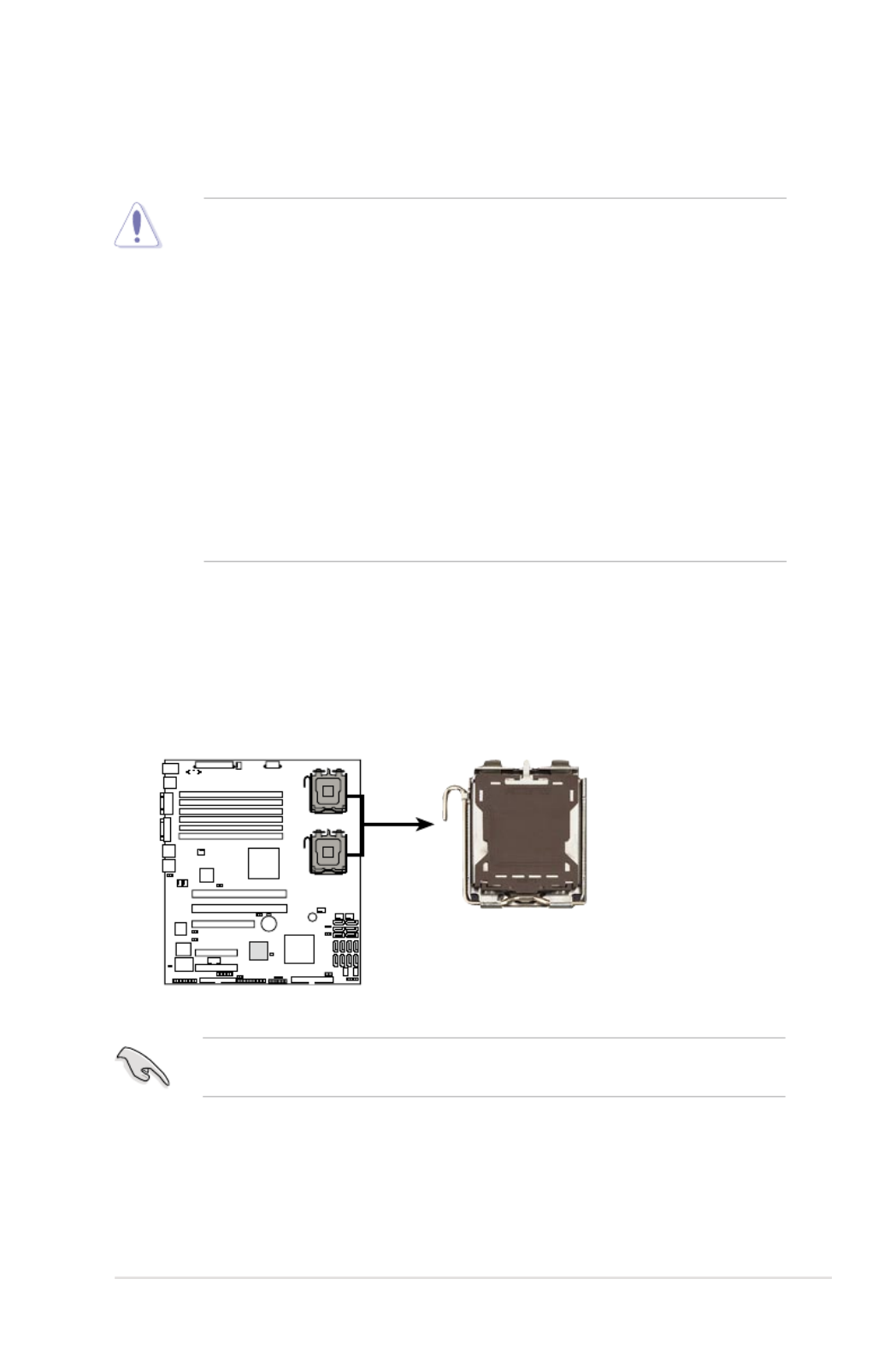
2.3.1 Installing the CPU
To install a CPU:
1. Locate the CPU socket on the motherboard.
2.3 Central Processing Unit (CPU)
The motherboard comes with a surface mount LGA771 socket designed for the
Intel® Xeon ® Dual Core processor.
Before installing the CPU, make sure that the socket box is facing towards you
and the load lever is on your left.
• Your boxed Intel ® Xeon ® LGA771 processor package should
come with installation instructions for the CPU and heatsink. If the
instructions in this section do not match the CPU documentation, follow the
latter.
•
Upon purchase of the motherboard, make sure that the PnP cap is on
the socket and the socket contacts are not bent. Contact your retailer
immediately if the PnP cap is missing, or if you see any damage to the PnP
cap/socket contacts/motherboard components. ASUS will shoulder the cost
of repair only if the damage is shipment/transit-related.
•
Keep the cap after installing the motherboard. ASUS will process Return
Merchandise Authorization (RMA) requests only if the motherboard comes
with the cap on the LGA771 socket.
• The product warranty does not cover damage to the socket contacts
resulting from incorrect CPU installation/removal, or misplacement/loss/
incorrect removal of the PnP cap.
DSBV-DX
DSBV-DX Series CPU LGA771
CPU1
CPU2

2-12 Chapter 2: Hardware information
3. Lift the load lever in the direction of
the arrow to a 135º angle.
4. Lift the load plate with your
thumb and forenger to a 100º
angle (A), then push the PnP
cap from the load plate window
to remove (B).
To prevent damage to the socket pins, do not remove the PnP cap unless you
are installing a CPU.
5. Position the CPU over
the socket, making sure
that the gold triangle
is on the bottom-left
corner of the socket.
The socket alignment
key should t into the
CPU notch.
Alignment key
Gold triangle mark
Load plate
A
B
2. Press the load lever with your thumb (A), then move it to the left (B) until it is
released from the retention tab.
Retention tab
Load lever
This side of the socket box
should face you.
PnP cap
A
B

ASUS DSBV-DX Series 2-13
Notes on Intel ® Hyper-Threading Technology
• This motherboard supports Intel
® Xeon™ CPUs in the 771-land package
with Hyper-Threading Technology.
• Hyper-Threading Technology is supported by Intel
® 5000 series CPU only.
5100/5300 series DO NOT support Hyper-Threading.
• The amount of CPU threads depends on the OS support.
• Hyper-Threading Technology is supported under Windows
® XP/2003 Server
and Linux 2.4.x (kernel) and later versions only. Under Linux, use the
Hyper-Threading compiler to compile the code. If you are using any other
operating systems, disable the Hyper-Threading Technology item in the
BIOS to ensure system stability and performance.
• Installing Windows® 2003 Server or later version is recommended.
• Make sure to enable the Hyper-Threading Technology item in BIOS before
installing a supported operating system.
• For more information on Hyper-Threading Technology, visit www.intel.
com/info/hyperthreading.
To use the Hyper-Threading Technology on this motherboard:
1. Install an Intel® Xeon™ CPU that supports Hyper-Threading Technology.
2. Power up the system and enter the BIOS Setup (see Chapter 4: BIOS
setup). Under the Advanced Menu, make sure that the item Hyper-Threading
Technology is set to Enabled. The item appears only if you installed a CPU
that supports Hyper-Threading Technology.
3. Reboot the computer.
The CPU ts in only one correct orientation. DO NOT force the CPU into the
socket to prevent bending the connectors on the socket and damaging the CPU!
6. Close the load plate (A), then
push the load lever (B) until it
snaps into the retention tab.
A
B

2-14 Chapter 2: Hardware information
The Intel® Xeon™ processors require an Intel certied heatsink and fan assembly
to ensure optimum thermal condition and performance.
When you buy a boxed Intel CPU, the package includes the heatsink, fan,
retention brackets, screws, thermal grease, installation manual, and other items
that are necessary for CPU installation.
2.3.2 Installing the CPU heatsink and fan
•
Make sure that you have applied the thermal grease to the top of the CPU
before installing the heatsink and fan.
•
Refer to the installation manual that came with the CPU package for details
on heatsink/fan assembly and installation.
CPU heatsink (top view) CPU heatsink (bottom view)
Heatsink screw
To install the CPU heatsink and fan:
1. Place the heatsink on top of the
installed CPU, making sure that the
four screws on the heatsink align
with the nuts on the support plate.

ASUS DSBV-DX Series 2-15
4. Repeat steps 1 to 3 to install the other heatsink if you have installed a second
CPU, then connect the fan cable to the 4-pin connector labeled CPU_FAN2.
2. Use a Phillips screwdriver to tighten
the four heatsink screws in a
diagonal sequence.
DO NOT forget to connect
the CPU fan cable! Hardware
monitoring errors may occur if
you fail to plug this connector.
3. Connect the fan cable to the 4-pin
connector labeled CPU_FAN1.
CPU_FAN1
connector

2-16 Chapter 2: Hardware information
2.4 System memory
2.4.1 Overview
The motherboard comes with six fully-buffered DIMM (FB-DIMM) sockets to
support 240-pin FB-DIMM modules. An FB-DIMM module has a different pin-out
from DDR2 DIMMs so you cannot install DDR2 DIMMs on an FB-DIMM socket.
Note that an FB-DIMM socket has an Advanced Memory Buffer (AMB) chip that
allows memory-to-CPU connection at gigabit speed.
The gure illustrates the location of the FB-DIMM sockets:
2.4.2 Memory congurations
You may install 256 MB, 512 MB, 1 GB, 2 GB, and 4 GB registered ECC
FB-DIMMs into the DIMM sockets.
• For optimum compatibility, we recommend that you obtain memory modules
from the same vendor. Refer to the Qualied Vendors List on the ASUS
web site.
• This motherboard does not support memory modules made up of 128 Mb
chips or double-rank x16 memory modules.
• If you are installing only one memory module, install into the white socket
labeled DIMM_00. Installing into any other socket will not work.
DSBV-DX
DSBV-DX Series 240-pin DIMM sockets
DIMM_01
DIMM_00
112 Pins128 Pins
DIMM_10
DIMM_02
DIMM_12
DIMM_11

ASUS DSBV-DX Series 2-17
Rank population
DIMM 12
DIMM 11
DIMM 10
DIMM 02
DIMM 01
DIMM 00
Channel
Slot 0
Slot 1
Ch:0
Slot 2
Slot 0
Slot 1
Slot 2
Ch:1
MCH
DIMM installation reference table
• DIMMs in pair means two DIMMs with the same conguration.
• For better performance, same conguration DIMMs should be installed on
the same slot number for each channel. For example, you may install the
same type of DIMMs in DIMM_00, and DIMM_10.
No. of DIMMs Slot/s to use
1 DIMM_00
2 DIMM_00, DIMM_10
4 DIMM_00, DIMM_01, DIMM_10, DIMM_11
6 DIMM_00, DIMM_01, DIMM_02, DIMM_10,
DIMM_11, DIMM_12

2-18 Chapter 2: Hardware information
2.4.3 Memory sparing technology
The Intel ® 5000V chipset supports the memory sparing technology. Refer to the
below sections:
Memory Sparing :
At conguration time, a DIMM rank is set aside to replace a defective DIMM rank.
When the error rate for a failing DIMM rank reaches a pre-determined threshold,
the memory sparing function will issue an interrupt and initiate a spare copy. At the
completion of the copy, the failing DIMM rank is disabled and the “spared” DIMM
rank will be used in its place. Refer to 4.4.2 Chipset Conguration and congure
the options of Branch 0 Rank Sparing to enable the memory sparing functions.
And the default BIOS setting is disabled.
• The DIMM rank with the largest size will be assigned as spare rank. Data
can only be copied from a smaller sized rank to a larger sized one.
• A DIMM can contain only one or two ranks. To support sparing function, a
DIMM channel should contain at least two ranks.
• When sparing function is enabled, the usable memory size will reduce then
size of the spare ranks.
Channel 0 Channel 1
DIMM_00
(2048MB/2 Ranks)
DIMM_10
(2048MB/2 Ranks)
Rank 0
(1024 MB)
Rank 1
(1024 MB)
Rank 0
(1024 MB)
Rank 1
(1024 MB)
Sparing V V
Memory space 1024 MB 1024 MB
Total Memory 2048 MB
The following tables show memory congurrations with Memory Sparing function in
Branch 0.
One DIMM per channel (Dual ranks)
2-20 Chapter 2: Hardware information
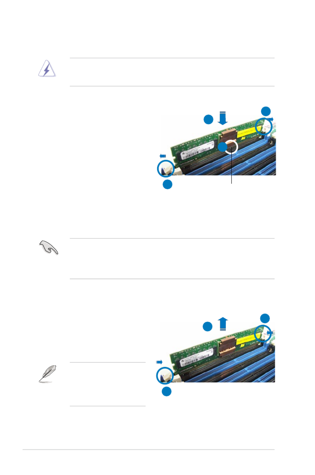
2.4.4 Installing a DIMM
Make sure to unplug the power supply before adding or removing DIMMs or
other system components. Failure to do so may cause severe damage to both
the motherboard and the components.
To install a DIMM:
1. Unlock a DIMM socket by pressing
the retaining clips outward.
2. Align a DIMM on the socket
such that the notch on the DIMM
matches the break on the socket.
3. Firmly insert the DIMM into the
socket until the retaining clips
snap back in place and the DIMM
is properly seated.
2.4.5 Removing a DIMM
To remove a DIMM:
1. Simultaneously press the retaining
clips outward to unlock the DIMM.
2. Remove the DIMM from the socket.
• A FB-DIMM is keyed with a notch so that it ts in only one direction. Do not
force a DIMM into a socket to avoid damaging the DIMM.
• The FB-DIMM sockets do not support DDR DIMMs. DO NOT install DDR
DIMMs to the DDR2 DIMM sockets.
Support the DIMM lightly with
your ngers when pressing
the retaining clips. The DIMM
might get damaged when it
ips out with extra force.
3
1
1
DDR2 DIMM notch
2
2
1
1
ASUS DSBV-DX Series 2-21
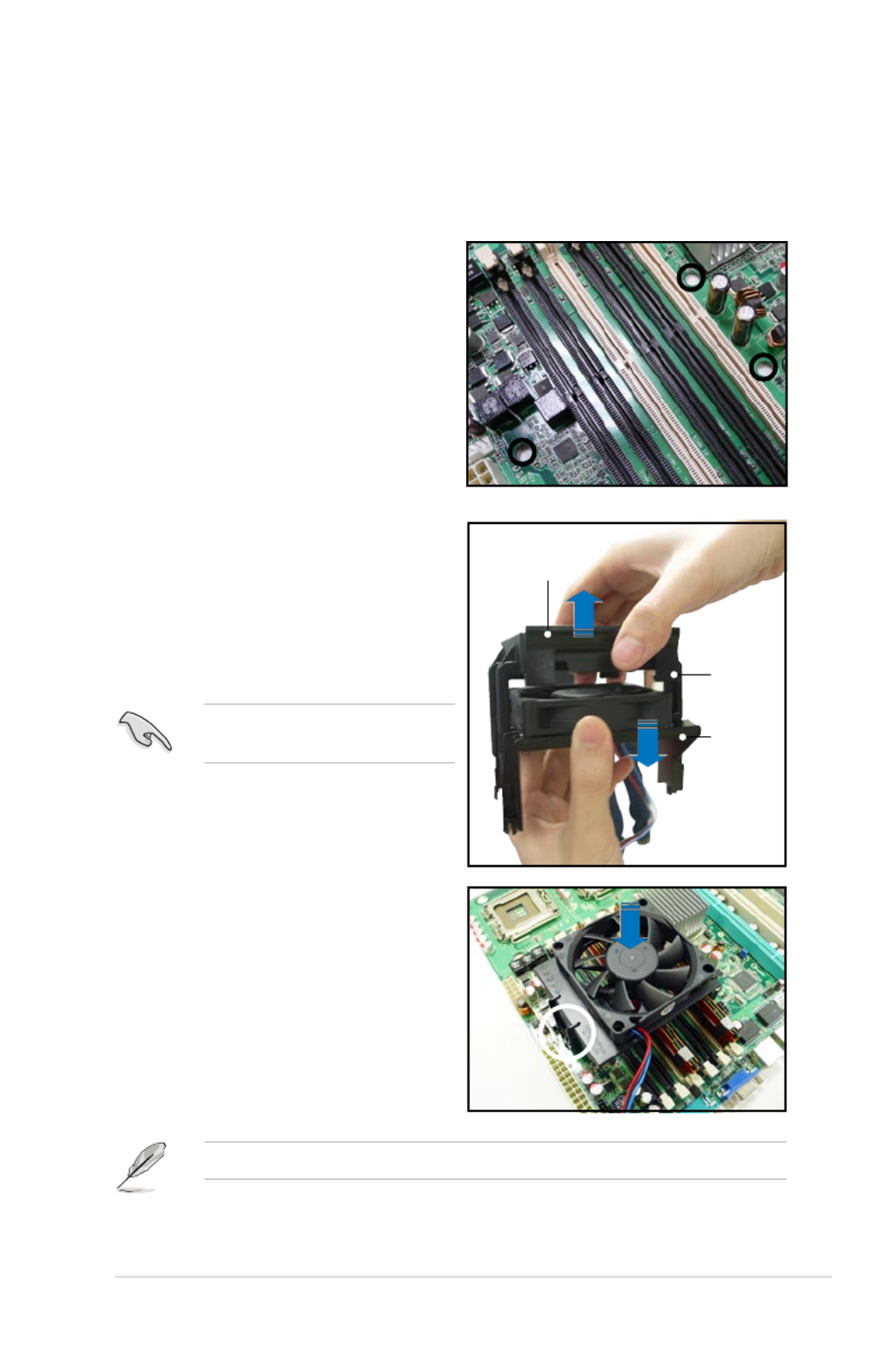
The FB-DIMMs generate heat during continued operation. To ensure optimum
thermal condition and performance, install the optional MemCool FB-DIMM fan.
To install the optional FB-DIMM fan:
1. Locate the three FB-DIMM fan holes
on the motherboard.
2.4.6 Installing the MemCool FB-DIMM fan (opional)
2. Disengage the fan top cover from the
fan base. You can do this by rmly
gripping the top cover by the clamps
to release the hooks, then pull up the
top cover carefully until it separates
from the fan base.
DO NOT remove the fan from the
fan base.
3. Position the fan base over the
DIMMs, and insert the fan base
legs into the FB-DIMM holes until
the legs are securely in place.
For instructional purposes only, no FB-DIMM is installed on any of the slots.
Top cover
hook
Top cover
clamp
Fan
base

2-22 Chapter 2: Hardware information
5. Connect the fan cable to the
4-pin connector labeled FBD_FAN1.
4. Position top cover over the fan
base. Insert the top cover legs into
the slot on the fan base legs.
Push down carefully until the legs
are securely in place and the top
cover hooks snap in place.
Make sure the cables pass
through the notch on the fan base
as shown.

ASUS DSBV-DX Series 2-23
2.4.7 Uninstalling the optional MemCool FB-DIMM fan
1. Unplug the fan cable.
2. Grip the top cover clamps until the
top cover hooks are released, then
carefully lift the top cover while
supporting the fan base with your
free hand.
3. Carefully lift the fan base.
Top cover clamp

ASUS DSBV-DX Series 2-25
2.5.3 Interrupt assignments
Standard interrupt assignments
IRQ Priority Standard Function
0 1 System Timer
1 2 Keyboard Controller
2 — Re-direct to IRQ#9
3 11 Communications Port (COM2)*
4 12 Communications Port (COM1)*
5 13 IRQ holder for PCI steering*
6 14 Floppy Disk Controller
7 15 Printer Port (LPT1)*
8 3 System CMOS/Real Time Clock
9 4 IRQ holder for PCI steering*
10 5 IRQ holder for PCI steering*
11 6 IRQ holder for PCI steering*
12 7 PS/2 Compatible Mouse Port*
13 8 Numeric Data Processor
14 9 Primary IDE Channel
15 10 Secondary IDE Channel
* These IRQs are usually available for ISA or PCI devices.
2-26 Chapter 2: Hardware information
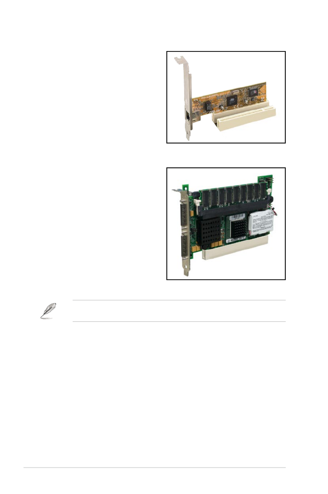
2.5.4 PCI/PCI-X slots
The PCI/PCI-X slots support cards such
as a LAN card, SCSI card, USB card,
and other cards that comply with PCI 2.3
and PCI-X 1.0 specications. The gure
shows a LAN card installed on a PCI slot.
32-bit PCI slot
64-bit PCI-X slot
The gure shows a RAID card installed
on a PCI-X slot.
When installing an optional ZCR card, install the card on PCIX1 slot (colored
green on DSBV-DX/SAS model).

ASUS DSBV-DX Series 2-27
2.5.5 PCI Express x8 slots (x8 and p49-x4 link)
2.5.6 ZCR slot
(DSBV-DX/SAS model only)
ZCR slot
The optional ZCR card for DSBV-DX/SAS onboard LSI 1068 SAS controller is
LSI MegaRAID SAS 8300XLP card. Visit the LSI LOGIC website (www.lsilogic.
com) for more information.
The onboard PCI Express x8 slots provides
x8 link (PCIE5) and p49-x4 link (PCIE4) to the
ESB2. This slot is designed for various
server class high performance add-on cards
like SCSI RAID card, ber-channel card,
etc.
The 64bit PCI-X slot (green) on the
motherboard supports a Zero-Channel
RAID card that allows RAID0, RAID1,
RAID10 and RAID 5 congurations.
PCIE x 8 slots
2-28 Chapter 2: Hardware information
Except when clearing the RTC RAM, never remove the cap on CLRTC jumper
default position. Removing the cap will cause system boot failure!
2.6 Jumpers
1. Clear RTC RAM (CLRTC1)
This jumper allows you to clear the Real Time Clock (RTC) RAM in CMOS.
You can clear the CMOS memory of date, time, and system setup parameters
by erasing the CMOS RTC RAM data. The onboard button cell battery
powers the RAM data in CMOS, which include system setup information such
as system passwords.
To erase the RTC RAM:
1. Turn OFF the computer and unplug the power cord.
2. Remove the onboard battery.
3. Move the jumper cap from pins 1-2 (default) to pins 2-3. Keep the cap on
pins 2-3 for about 5~10 seconds, then move the cap back to pins 1-2.
4. Reinstall the battery.
5. Plug the power cord and turn ON the computer.
6. Hold down the <Del> key during the boot process and enter BIOS setup
to re-enter data.
DSBV-DX
DSBV-DX Series Clear RTC RAM
CLRTC1
Normal
(Default)
Clear CMOS
1 2 2 3
ASUS DSBV-DX Series 2-29
2. LAN bandwidth setting (3-pin LAN_BW1)
This jumper allows you to set the LAN bandwidth setting for more efcient IP
load distribution.
DSBV-DX
DSBV-DX Series LAN bandwidth setting
LAN_BW1
Balanced mode
(Default)
Centric mode
2 31 2
3. VGA controller setting (3-pin VGA_EN1)
These jumpers allow you to enable or disable the onboard VGA controller.
Set to pins 1-2 to activate the VGA feature.
DSBV-DX
DSBV-DX Series VGA setting
VGA_EN1
1 2 2 3
Enable
(Default)
Disable

2-30 Chapter 2: Hardware information
4. LAN controller setting (3-pin LAN_EN1)
This jumper allows you to enable or disable the onboard Intel ® 82563EB
Gigabit LAN controller. Set to pins 1-2 to activate the Gigabit LAN feature.
DSBV-DX
DSBV-DX Series LAN_EN1 setting
LAN_EN1
1 2 2 3
Enable
(Default)
Disable
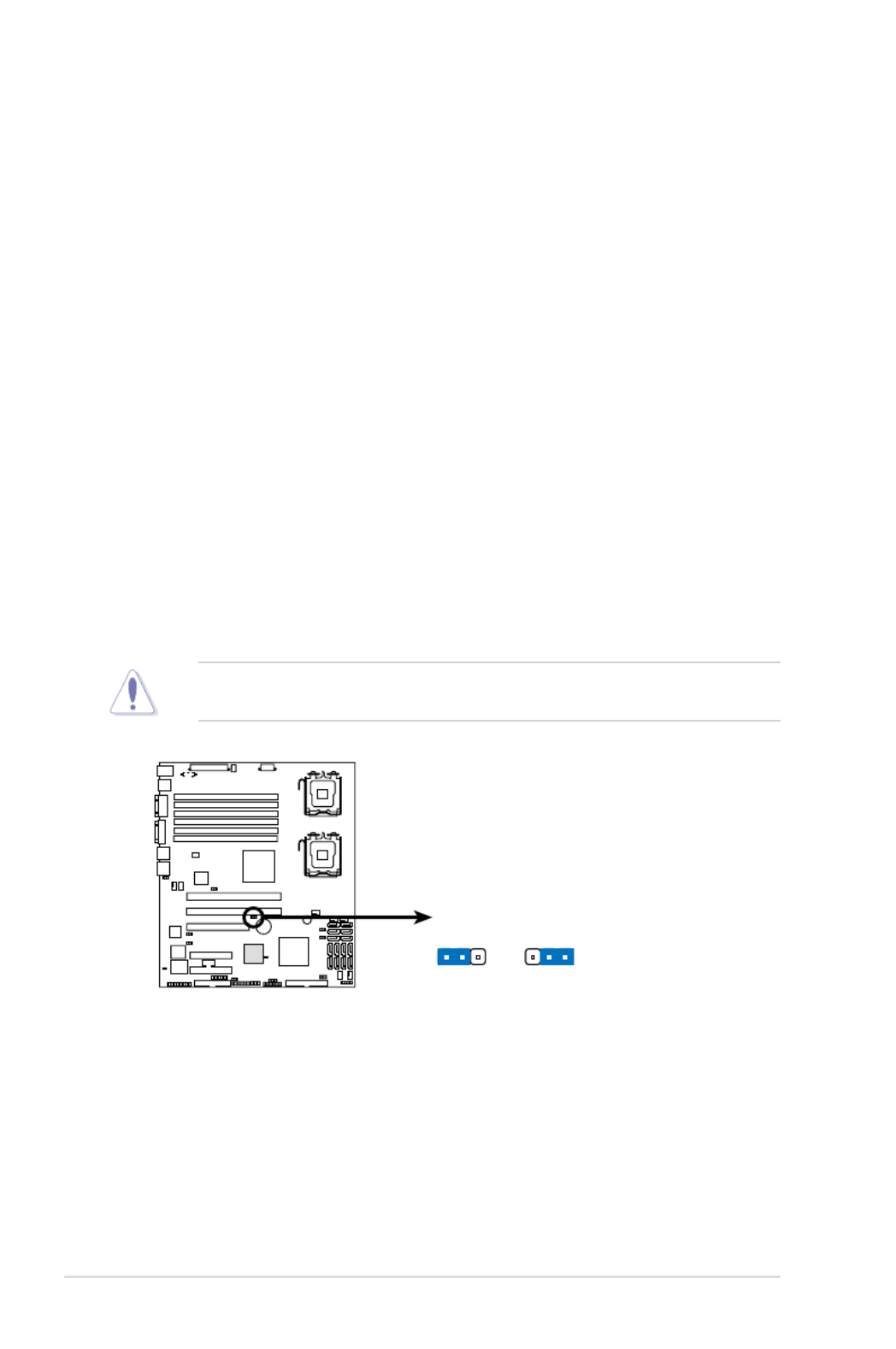
5. Fan control setting (3-pin FAN_SEL1)
This jumper allows you to switch for fan pin selection Set to pins 1-2 for 4-pin
fans or pins 2-3 for 3-pin fans.
21 32
DSBV-DX
DSBV-DX Series Fan setting
FAN_SEL1
(Default)
4-pin FAN 3-pin FAN
•
If you use a 4-pin fan but set the jumper to pin 2-3, the fan you installed
may not work.
•
If you use a 3-pin fan but set the jumper for a 4-pin fan, the fan controll will
not work and the fan you installed will always run at full speed.

ASUS DSBV-DX Series 2-31
6. Intel® 6321ESB SATA port S/W RAID setting (3-pin RAID_SEL1)
(DSBV-DX models only)
This jumper allows you to select the Serial ATA RAID conguration utility to
use when you create disk arrays. Both utilities are supported by the Intel
® 6321ESB. Place the jumper caps on pins 1-2 if you want to use the LSI
MegaRAID Serial ATA RAID utility (default); otherwise, place the jumper caps
on pins 2-3 to use the Intel® Matrix Storage Manager (IMSM).
DSBV-DX
DSBV-DX Series 6321ESB SATA port S/W RAID setting
RAID_SEL1
3rd party RAID
(Intel® IMSM)
3rd party RAID
(LSI MegaRAID)
(Default)
1 2 2 3
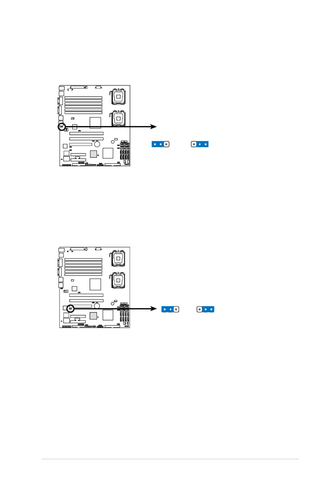
7. Onboard storage setting (3-pin SAS_EN1)
(DSBV-DX/SAS model only)
This jumper allows you to enable or disable the onboard LSI1068 SAS
controller. Set the jumper to pins 1-2 to enable the SAS function (default).
DSBV-DX
DSBV-DX Series SAS setting
SAS_EN1
1 2 2 3
Enable
(Default)
Disable

ASUS DSBV-DX Series 2-33
2.7 Connectors
2.7.1 Rear panel connectors
LAN port LED indications
LAN port
SPEED
LED
ACT/LINK
LED
4. Serial (COM1) port . This 9-pin communication port is for pointing devices or
other serial devices.
5. Video Graphics Adapter port . This port is for a VGA monitor or other VGA-
compatible devices.
6. LAN (RJ-45) ports . These ports allow Gigabit connection to a Local Area
Network (LAN) through a network hub. Refer to the table below for the LAN
port LED indications.
1. PS/2 mouse port (green) . This port is for a PS/2 mouse.
2. PS/2 keyboard port (purple) . This port is for a PS/2 keyboard.
3. USB 2.0 ports 1 and 2 . These two 4-pin Universal Serial Bus (USB) ports
are available for connecting USB 2.0 devices.
1
2 3 64 5
Activity/Link Speed LED
Status Description Status Description
OFF No link OFF 10 Mbps connection
ORANGE Linked ORANGE 100 Mbps connection
BLINKING Data activity GREEN 1 Gbps connection

2-34 Chapter 2: Hardware information
2. IDE connector (40-1 pin PRI_IDE1)
This connector is for an Ultra DMA 100/66 signal cable. The Ultra
DMA 100/66 signal cable has three connectors: a blue connector for the
primary IDE connector on the motherboard, a black connector for an Ultra
DMA 100/66 IDE slave device (optical drive/hard disk drive), and a gray
connector for an Ultra DMA 100/66 IDE master device (hard disk drive). If you
install two hard disk drives, you must congure the second drive as a slave
device by setting its jumper accordingly. Refer to the hard disk documentation
for the jumper settings.
2.8.2 Internal connectors
1. Floppy disk drive connector (34-1 pin FLOPPY1)
This connector is for the provided oppy disk drive (FDD) signal cable. Insert
one end of the cable to this connector, then connect the other end to the
signal connector at the back of the oppy disk drive.
Pin 5 on the connector is removed to prevent incorrect cable connection when
using a FDD cable with a covered Pin 5.
• Pin 20 on the IDE connector is removed to match the covered hole on the
Ultra DMA cable connector. This prevents incorrect insertion when you
connect the IDE cable.
• Use the 80-conductor IDE cable for Ultra DMA 100/66 IDE devices.
DSBV-DX
NOTE: Orient the red markings on
the floppy ribbon cable to PIN 1.
PIN 1
FLOPPY1
DSBV-DX Series Floppy disk drive connector
DSBV-DX
DSBV-DX Series IDE connector
PRI_IDE1
PIN 1
NOTE: Orient the red markings
(usually zigzag) on the IDE
ribbon cable to PIN 1.
ASUS DSBV-DX Series 2-35
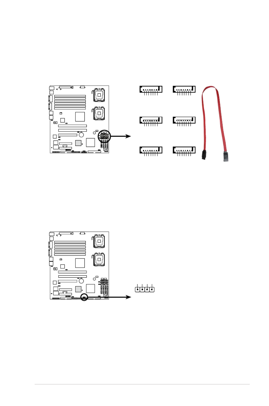
3. Serial ATA connectors
(7-pin SATA1, SATA2, SATA3, SATA4, SATA5, SATA6 )
These connectors are for the Serial ATA signal cables for Serial ATA hard disk
drives.
4. Hard disk activity LED connector (4-pin HDLED1)
This connector is used to connect to a hard disk drive active LED connector
on the SCSI or RAID card.
DSBV-DX
SATA2
SATA1
DSBV-DX Series SATA connectors
SATA4
SATA3 SATA6
SATA5
GND
RSATA_TXP1
RSATA_TXN1
GND
RSATA_RXN1
RSATA_RXP1
GND
GND
RSATA_TXP2
RSATA_TXN2
GND
RSATA_RXN2
RSATA_RXP2
GND
GND
RSATA_TXP3
RSATA_TXN3
GND
RSATA_RXN3
RSATA_RXP3
GND
GND
RSATA_TXP4
RSATA_TXN4
GND
RSATA_RXN4
RSATA_RXP4
GND
GND
RSATA_TXP5
RSATA_TXN5
GND
RSATA_RXN5
RSATA_RXP5
GND
GND
RSATA_TXP6
RSATA_TXN6
GND
RSATA_RXN6
RSATA_RXP6
GND
DSBV-DX
DSBV-DX Series storage card activity LED connector
HDLED1
PIN1
ADD_IN_CARD-
NC
NC
ADD_IN_CARD-
2-36 Chapter 2: Hardware information
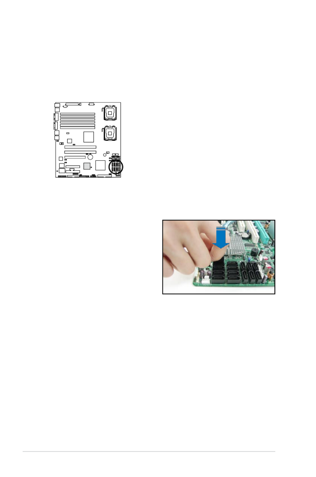
5. SAS connectors
(DSBV-DX/SAS model only)
This motherboard comes with eight blue Serial Attached SCSI (SAS)
connectors, the next-generation storage technology that supports both Series
SCSI and Serial ATA (SATA). Each connector supports one device.
To connect the SAS cable:
Plug in the SAS cable to the
SAS1-8 connector until the cable
snaps in place.
DSBV-D X
DSBV-DX Series SAS connectors

ASUS DSBV-DX Series 2-37
6. SAS LSI1068 ports LED connector (18-1 pin SASLED1)
(DSBV-DX/SAS model only)
This connector is for the front panel LED port indicator that shows the SAS
HDD status.
DSBV-DX
DSBV-DX Series SAS LED connector
SASLED1
ACT_LED0 FLT_LED0
PIN 1
ACT_LED1 FLT_LED1
ACT_LED2 FLT_LED2
ACT_LED3 FLT_LED3
ACT_LED4 GND
ACT_LED5 FLT_LED4
FLT_LED5
ACT_LED6 FLT_LED6
ACT_LED7 FLT_LED7
7. Serial General Purpose Input/Output connector (6-1 pin SGPIO1)
This connector is used for the SGPIO peripherals for the LSI MegaRAID
SATA LED.
DSBV-DX
DSBV-DX Series SGPIO connector
SGPIO1
PIN1
GND
SATA_SCLK
SATA_SLOAD
SDATAOUT1
SDATAOUT0

2-38 Chapter 2: Hardware information
9. Serial port connector (10-1 pin COM2)
This connector is for a serial (COM) port. Connect the serial port module
cable to this connector, then install the module to a slot opening at the back
of the system chassis.
The serial port module is purchased separately.
8. USB connector (10-1 pin USB34)
This connector is for USB 2.0 ports. Connect the USB module cable to
this connector, then install the module to a slot opening at the back of the
system chassis. This USB connector complies with USB 2.0 specication that
supports up to 480 Mbps connection speed.
The USB port module is purchased separately.
DSBV-DX
DSBV-DX Series USB connector
USB34
Power
PIN1
USB PortA(-)
USB PortA(+)
GND
Power
USB PortB(-)
USB PortB(+)
GND
NC
DSBV-DX
DSBV-DX Series Serial port connectors
PIN1
COM2
ASUS DSBV-DX Series 2-39
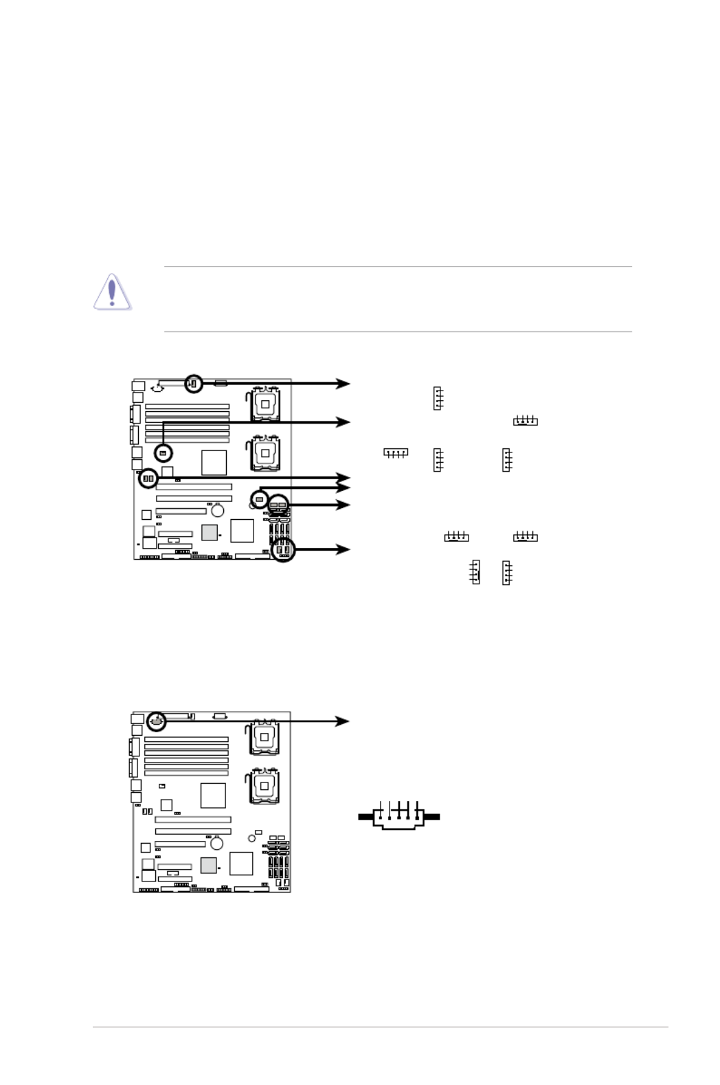
10. CPU and system fan connectors (4-pin CPU_FAN1/2, REAR_FAN1/2,
FRNT_FAN1/2/3/4, FBD_FAN1)
The fan connectors support cooling fans of 350 mA ~ 740 mA (8.88 W max.)
or a total of 3.15 A ~ 6.66 A (53.28 W max.) at +12V. Connect the fan cables
to the fan connectors on the motherboard, making sure that the black wire of
each cable matches the ground pin of the connector.
DO NOT forget to connect the fan cables to the fan connectors. Insufcient air
ow inside the system may damage the motherboard components. These are
not jumpers! DO NOT place jumper caps on the fan connectors!
11. Power supply SMBus connector (5-pin PSUSMB1)
This connector is for the power supply SMB cable, if your power supply
supports the SMBus function.
DSBV-DX
DSBV-DX Series Fan connectors
CPU_FAN1
CPU_FAN2
REAR_FAN1
REAR_FAN2
FRNT_FAN1
FRNT_FAN2
FRNT_FAN3
FRNT_FAN4
FBD_FAN1
CPU_FAN1 CPU_FAN2
GND
FAN Power
FAN Speed
PWM Control
REAR_FAN1 REAR_FAN2
GND
FAN Power
FAN Speed
PWM Control
FRNT_FAN1 FRNT_FAN2
FRNT_FAN3 FRNT_FAN4
FBD_FAN1
GND
FAN Power
FAN Speed
PWM Control
GND
FAN Power
FAN Speed
PWM Control
GND
FAN Power
FAN Speed
PWM ControlGND
FAN Power
FAN Speed
PWM Control
GND
FAN Power
FAN Speed
PWM Control
GND
FAN Power
FAN Speed
PWM Control
GND
FAN Power
FAN Speed
PWM Control
DSBV-DX
DSBV-DX Series Power supply SMBus connector
PSUSMB1
+3.3V Remote Sense
GND
NC
I2CDAT
I2CCLK

2-40 Chapter 2: Hardware information
12. SSI power connectors (24-pin ATXPWR1, 8-pin ATX12V1)
These connectors are for SSI power supply plugs. The power supply plugs
are designed to t these connectors in only one orientation. Find the proper
orientation and push down rmly until the connectors completely t.
•
For a fully congured system, we recommend that you use an SSI
12 V-compliant power supply unit (PSU) for LGA771-socket Intel ® Xeon
Dual Core processors (Bensley platform).
•
DO NOT forget to connect the 24+8-pin power plugs; otherwise, the system
will not boot up.
•
Use of a PSU with a higher power output is recommended when conguring
a system with more power consuming devices. The system may become
unstable or may not boot up if the power is inadequate.
•
You must install a PSU with a higher power rating if you intend to install
additional devices.
DSBV-DX
DSBV-DX Series ATX power connectors
8-PIN
GND
12V1
GND
12V1
GND
12V2
GND
12V2
24-PIN Power Connector
ATXPWR1
ATX12V1
+3 Volts
+3 Volts
Ground
+5 Volts
+5 Volts
Ground
Ground
Power OK
+5V Standby
+12 Volts
-5 Volts
+5 Volts
+3 Volts
-12 Volts
Ground
Ground
Ground
PSON#
Ground
+5 Volts
+12 Volts
+3 Volts
+5 Volts
Ground
ASUS DSBV-DX Series 2-41
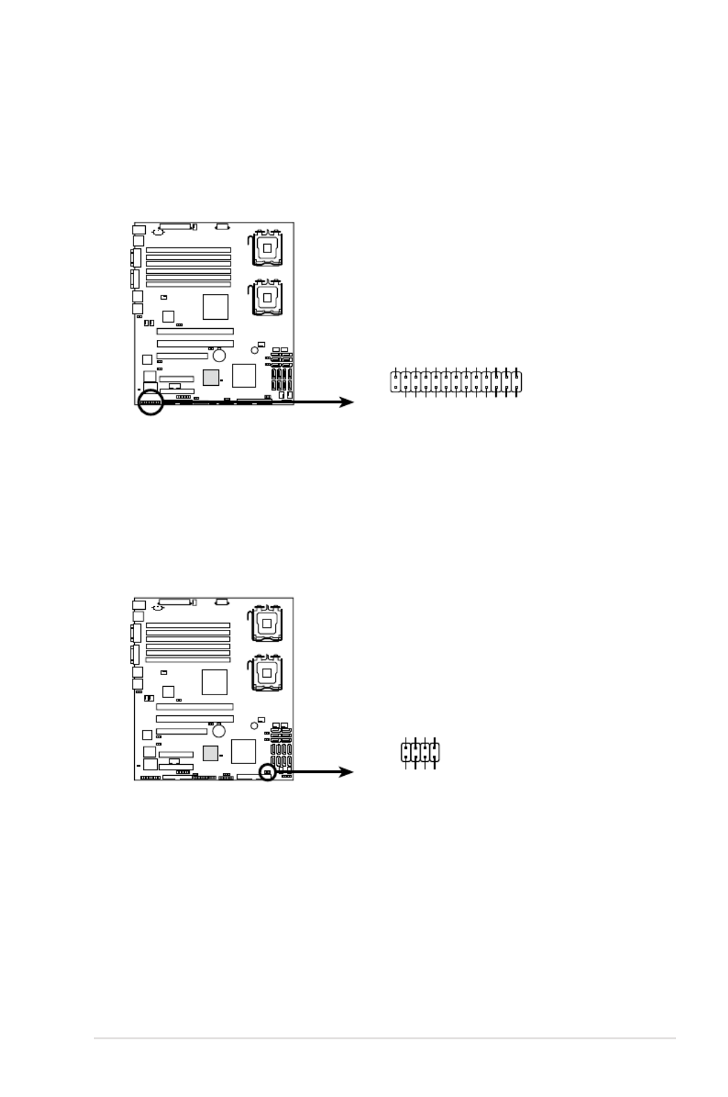
13. Parallel port connector (26-1 pin LPT1)
This connector is for a parallel port. Connect the parallel port module cable
to this connector, then install the module to a slot opening at the back of the
system chassis.
DSBV-DX
DSBV-DX Series Parallel port connector
LPT1
SPD7GND
SPD6GND
SPD5GND
SPD4GND
SLCT
PEGND
BUSY
ACK#GND
SPD3GND
SPD2SLIN#
SPD1PINIT#
SPD0ERROR#
STB#AFD#
GND
PIN1
14. Serial General Purpose Input/Output connector (2x4 pin SGPIO2)
(DSBV-DX/SAS model only)
This connector is used for the SGPIO peripherals for the LSI MegaRAID.
DSBV- DX
DSBV-DX Series SGPIO connector
SGPIO2
SCLK_A
PIN1
SIOEND_A
SDOUT_A
SDIN_A
SCLK_B
SIOEND_B
SDOUT_B
SDIN_B
2-42 Chapter 2: Hardware information
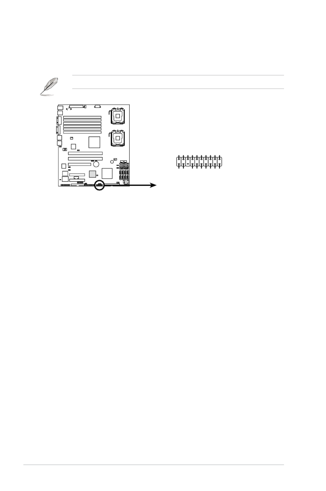
15. System panel connector (20-pin PANEL1)
This connector supports several chassis-mounted functions.
The system panel connector is color-coded for easy connection.
1.
System power LED (Green 3-pin PLED)
This 3-pin connector is for the system power LED. Connect the chassis
power LED cable to this connector. The system power LED lights up
when you turn on the system power, and blinks when the system is in
sleep mode.
2.
Message LED (Brown 2-pin MLED)
This 2-pin connector is for the message LED cable that connects to
the front message LED. The message LED is controlled by Hardware
monitor to indicate an abnormal event occurance.
3.
System warning speaker (Orange 4-pin SPEAKER)
This 4-pin connector is for the chassis-mounted system warning
speaker. The speaker allows you to hear system beeps and warnings.
4.
Hard disk drive activity LED (Red 2-pin IDE_LED)
This 2-pin connector is for the HDD Activity LED. Connect the HDD
Activity LED cable to this connector. The IDE LED lights up or ashes
when data is read from or written to the HDD.
5.
ATX power button/soft-off button (Green 2-pin PWRSW)
This connector is for the system power button. Pressing the power
button turns the system on or puts the system in sleep or soft-off mode
depending on the BIOS settings. Pressing the power switch for more
than four seconds while the system is ON turns the system OFF.
6.
Reset button (Blue 2-pin RESET)
This 2-pin connector is for the chassis-mounted reset button for system
reboot without turning off the system power.
DSBV-DX
DSBV-DX Series System panel connector
PANEL1
MLED-GND
NCPOWERBTN#
+5VGND
GNDNC
POWERLED+IDELED+
NCIDELED-
POWERLED-
MLED+NMIBTN#
GNDRESETBTN#
SPKROUTGND

2-44 Chapter 2: Hardware information

3
Powering up
This chapter describes the power up
sequence, and ways of shutting down the
system.

ASUS DSBV-DX Series
Chapter summary
3
3.1 Starting up for the rst time ........................................................ 3-1
3.2 Turning off the computer ............................................................. 3-2

ASUS DSBV-DX Series 3-1
3.1 Starting up for the rst time
1. After making all the connections, replace the system case cover.
2. Be sure that all switches are off.
3. Connect the power cord to the power connector at the back of the system
chassis.
4. Connect the power cord to a power outlet that is equipped with a surge
protector.
5. Turn on the devices in the following order:
a. Monitor
b. System power
6. After applying power, the system power LED on the system front panel case
lights up. For systems withATX power supplies, the system LED lights up
when you press the ATX power button. If your monitor complies with “green”
standards or if it has a “power standby” feature, the monitor LED may light up
or switch between orange and green after the system LED turns on.
The system then runs the power-on self tests or POST. While the tests are
running, the BIOS beeps (see BIOS beep codes table below) or additional
messages appear on the screen. If you do not see anything within 30
seconds from the time you turned on the power, the system may have failed a
power-on test. Check the jumper settings and connections or call your retailer
for assistance.
Phoenix BIOS beep codes
Beep Description Error
Endless beep Memory module missing
One continuous beep followed by VGA controller failure
short beeps
Two short beeps PCI resource assignment error
7. At power on, hold down the <Delete> key to enter the BIOS Setup. Follow the
instructions in Chapter 4.

3-2 Chapter 3: Powering up
3.2 Turning off the computer
3.2.1 Using the OS shut down function
If you are using Windows ® 2000/2003:
1. Click the Start button then click Shut Down ...
2. Make sure that the Shut Down option button is selected, then click the OK
button to shut down the computer.
3. The power supply should turn off after Windows ® shuts down.
If you are using Windows ® XP:
1. Click the Start button then select Turn Off Computer.
2. Click the Turn Off button to shut down the computer.
3. The power supply should turn off after Windows ® shuts down.
3.2.2 Using the dual function power switch
While the system is ON, pressing the power switch for less than four seconds puts
the system to sleep mode or to soft-off mode, depending on the BIOS setting.
Pressing the power switch for more than four seconds lets the system enter the
soft-off mode regardless of the BIOS setting.

4
BIOS setup
This chapter tells how to change the
system settings through the BIOS Setup
menus. Detailed descriptions of the BIOS
parameters are also provided.
Produktspezifikationen
| Marke: | Asus |
| Kategorie: | Server |
| Modell: | DSBV-DX |
| Prozessorhersteller: | Intel |
| Anzahl USB 2.0 Anschlüsse: | 2 |
| Betriebstemperatur: | 10 - 35 °C |
| Anzahl Ethernet-LAN-Anschlüsse (RJ-45): | 1 |
| RAID Level: | 0, 1 |
| Prozessorsockel: | LGA 771 (Socket J) |
| Anzahl VGA (D-Sub) Anschlüsse: | 1 |
| Motherboardformfaktor: | SSI CEB |
| Motherboard Chipsatz: | Intel® 5000V |
| ECC: | Ja |
| RAM-Speicher maximal: | 24 GB |
| Anzahl PS/2 Anschlüsse: | 2 |
| ATX Stromstecker (24-pol.): | Ja |
| Anzahl USB 2.0 Schnittstellen: | 1 |
| Chassis Intrusion Stecker: | Ja |
| LAN-Controller: | Intel® 82563EB |
| Mitgelieferte Software: | MemCool Kit\nCA eTrust Anti-virus |
| Zahl der parallelen ATA Stecker: | 1 |
| Anzahl serielle Anschlüsse: | 1 |
| Power Fan Connector: | Ja |
| SATA Anschlüsse: | 6 |
| RAID-Controller Type: | Intel Matrix Storage/LSI MegaRAID |
Brauchst du Hilfe?
Wenn Sie Hilfe mit Asus DSBV-DX benötigen, stellen Sie unten eine Frage und andere Benutzer werden Ihnen antworten
Bedienungsanleitung Server Asus

31 August 2024
28 August 2024
20 August 2024
19 August 2024
16 August 2024
9 August 2024
8 August 2024
8 August 2024
7 August 2024
2 August 2024
Bedienungsanleitung Server
- Server Acer
- Server Gigabyte
- Server HP
- Server Medion
- Server Sony
- Server ZyXEL
- Server Buffalo
- Server Allnet
- Server Linksys
- Server Netgear
- Server Fantec
- Server Technics
- Server Abus
- Server Megasat
- Server Toshiba
- Server Lindy
- Server Dell
- Server Lenovo
- Server Tripp Lite
- Server TRENDnet
- Server Western Digital
- Server AVerMedia
- Server Veritas
- Server Black Box
- Server Supermicro
- Server SilverStone
- Server NEC
- Server Monacor
- Server Seagate
- Server Fujitsu
- Server Maxdata
- Server Revox
- Server Totolink
- Server Conceptronic
- Server D-Link
- Server QNAP
- Server Digitus
- Server LevelOne
- Server APC
- Server Cisco
- Server Freecom
- Server Synology
- Server Kramer
- Server Intellinet
- Server Eaton
- Server Hikvision
- Server FLIR
- Server ELAC
- Server Planet
- Server Asustor
- Server Blackmagic Design
- Server Dane Elec
- Server Digi
- Server Dual Bay
- Server EMC
- Server GeoVision
- Server Ibm
- Server In Win
- Server Iomega
- Server LaCie
- Server Provision ISR
- Server Quantum
- Server Sun
- Server AMX
- Server ACTi
- Server Vimar
- Server Siig
- Server Intel
- Server Moxa
- Server StarTech.com
- Server Smart-AVI
- Server Mobotix
- Server Sonnet
- Server SEH
- Server Gefen
- Server Avocent
- Server Atlantis Land
- Server Hanwha
- Server ATen
- Server KanexPro
- Server Axis
- Server Advantech
- Server HGST
- Server Kiloview
- Server B&B Electronics
- Server Extron
- Server Atlona
- Server Rocstor
- Server Raidsonic
- Server G-Technology
- Server Infortrend
- Server Areca
- Server Silex
- Server Promise Technology
- Server Matrox
- Server Origin Storage
- Server Ernitec
- Server EXSYS
- Server Raritan
- Server C2G
- Server Chenbro Micom
- Server Lantronix
- Server IStarUSA
- Server Valcom
- Server TAIDEN
- Server MvixUSA
- Server Opengear
- Server Mr. Signal
- Server NETSCOUT
Neueste Bedienungsanleitung für -Kategorien-

13 Oktober 2024

12 Oktober 2024
12 Oktober 2024

11 Oktober 2024
11 Oktober 2024

10 Oktober 2024
6 Oktober 2024

4 Oktober 2024
3 Oktober 2024
3 Oktober 2024