Asrock X99 OC FORMULA Bedienungsanleitung
Asrock
Hauptplatine
X99 OC FORMULA
Lesen Sie kostenlos die 📖 deutsche Bedienungsanleitung für Asrock X99 OC FORMULA (108 Seiten) in der Kategorie Hauptplatine. Dieser Bedienungsanleitung war für 15 Personen hilfreich und wurde von 2 Benutzern mit durchschnittlich 4.5 Sternen bewertet
Seite 1/108


Version 1.0
Published September 2014
Copyright©2014 ASRock INC. All rights reserved.
Copyright Notice:
No part of this documentation may be reproduced, transcribed, transmitted, or
translated in any language, in any form or by any means, except duplication of
documentation by the purchaser for backup purpose, without written consent of
ASRock Inc.
Products and corporate names appearing in this documentation may or may not
be registered trademarks or copyrights of their respective companies, and are used
only for identication or explanation and to the owners’ benet, without intent to
infringe.
Disclaimer:
Specications and information contained in this documentation are furnished for
informational use only and subject to change without notice, and should not be
constructed as a commitment by ASRock. ASRock assumes no responsibility for
any errors or omissions that may appear in this documentation.
With respect to the contents of this documentation, ASRock does not provide
warranty of any kind, either expressed or implied, including but not limited to
the implied warranties or conditions of merchantability or tness for a particular
purpose.
In no event shall ASRock, its directors, ocers, employees, or agents be liable for
any indirect, special, incidental, or consequential damages (including damages for
loss of prots, loss of business, loss of data, interruption of business and the like),
even if ASRock has been advised of the possibility of such damages arising from any
defect or error in the documentation or product.
is device complies with Part 15 of the FCC Rules. Operation is subject to the following
two conditions:
(1) this device may not cause harmful interference, and
(2) this device must accept any interference received, including interference that
may cause undesired operation.
CALIFORNIA, USA ONLY
e Lithium battery adopted on this motherboard contains Perchlorate, a toxic substance
controlled in Perchlorate Best Management Practices (BMP) regulations passed by the
California Legislature. When you discard the Lithium battery in California, USA, please
follow the related regulations in advance.
“Perchlorate Material-special handling may apply, see www.dtsc.ca.gov/hazardouswaste/
perchlorate”
ASRock Website: http://www.asrock.com

Manufactured under license under U.S. Patent Nos: 5,956,674; 5,974,380; 6,487,535;
7,003,467 & other U.S. and worldwide patents issued & pending. DTS, the Symbol, &
DTS and the Symbol together is a registered trademark & DTS Connect, DTS Interactive,
DTS Neo:PC are trademarks of DTS, Inc. Product includes soware.
© DTS, Inc., All Rights Reserved.

2.11.1 Installing Two CrossFireXTM-Ready Graphics Cards 41
2.11.2 Installing Three CrossFireXTM-Ready Graphics Cards 42
2.11.3 Installing Four CrossFireXTM-Ready Graphics Cards 43
2.11.4 Driver Installation and Setup 44
2.12 M.2_SSD (NGFF) Module Installation Guide 45
2.13 HDD Saver Cable Installation Guide 48
Chapter 3 Software and Utilities Operation 49
3.1 Installing Drivers 49
3.2 Formula Drive 50
3.3 ASRock APP Shop 56
3.3.1 UI Overview 56
3.3.2 Apps 57
3.3.3 BIOS & Drivers 60
3.3.4 Setting 61
3.4 Start8 62
Chapter 4 UEFI SETUP UTILITY 68
4.1 Introduction 68
4.1.1 UEFI Menu Bar 68
4.1.2 Navigation Keys 69
4.2 Main Screen 70
4.3 OC Tweaker Screen 71
4.4 Advanced Screen 81
4.4.1 CPU Conguration 82
4.4.2 Chipset Conguration 84

4.4.3 Storage Conguration 86
4.4.4 Super IO Conguration 87
4.4.5 ACPI Conguration 88
4.4.6 USB Conguration 89
4.4.7 Trusted Computing 90
4.5 Tools 91
4.6 Hardware Health Event Monitoring Screen 95
4.7 Security Screen 97
4.8 Boot Screen 98
4.9 Exit Screen 101

2
English
1.2 Specications
Platform EATX Form Factor
8 Layer PCB
4 x 2oz copper
High Density Glass Fabric PCB
CPU Supports Intel® CoreTM i7 and Xeon® 18-Core Processors
Family for the LGA 2011-3 Socket
Digi Power design
12 Power Phase design (Supports up to 1300w)
Supports Intel® Turbo Boost 2.0 Technology
Supports Untied Overclocking Technology
Chipset Intel® X99
Memory Quad Channel DDR4 Memory Technology
8 x DDR4 DIMM Slots
Supports DDR4 3400+(OC)*/2933(OC)/2800(OC)/2400
(OC)/2133/1866 non-ECC, un-buered memory
* Please refer to Memory Support List on ASRock's website for
more information. (http://www.asrock.com/)
Supports non-ECC p8-x8 (8 bit) RDIMM (Registered DIMM)/
x8 (8 bit) UDIMM
Supports DDR4 ECC x8 (8 bit) RDIMM/x8 (8 bit) UDIMM
with Intel® Xeon® processors E5 series in the LGA 2011-3
Socket
Max. capacity of system memory: 128GB
Supports Intel® Extreme Memory Prole (XMP) 2.0
Expansion
Slot
5 x PCI Express 3.0 x16 Slots (PCIE1/PCIE2/PCIE3/PCIE4/
PCIE5: single at x16 (PCIE1); dual at x16 (PCIE1) / x16
(PCIE4); triple at p8-x8 (PCIE1) / p8-x8 (PCIE2) / x16 (PCIE4);
quad at p8-x8 (PCIE1) / p8-x8 (PCIE2) / p8-x8 (PCIE4) / p8-x8 (PCIE5))
* If you install CPU with 28 lanes, PCIE1/PCIE2/PCIE3/PCIE4
will run at x16/x0/x4/x8 or x8/x8/x4/x8, and PCIE5 will be
disabled.
* If Ultra M.2 PCI Express module is installed, PCIE3 slot will
be disabled.
1 x Half Mini-PCI Express Slot

3
English
X99 OC Formula
Supports AMD Quad CrossFireXTM, 4-Way CrossFireXTM,
3-Way CrossFireXTM and CrossFireXTM
Supports NVIDIA® Quad SLITM, 4-Way SLITM, 3-Way SLITM
and SLITM
* If you install CPU with 28 lanes, 4-Way CrossFireXTM and
4-Way SLITM are not supported.
Audio 7.1 CH HD Audio with Content Protection (Realtek
ALC1150 Audio Codec)
Premium Blu-ray Audio support
Supports Surge Protection (ASRock Full Spike Protection)
Supports Purity Sound™ 2
- Nichicon Fine Gold Series Audio Caps
- 115dB SNR DAC with Dierential Amplier
- TI® NE5532 Premium Headset Amplier (Supports up to
600 Ohms headsets)
- Direct Drive Technology
- EMI Shielding Cover
- PCB Isolate Shielding
Supports DTS Connect
LAN 1 x Intel® I218V (Gigabit LAN PHY 10/100/1000 Mb/s)
1 x Qualcomm® Atheros® AR8171 (PCIE p9-x1 Gigabit LAN
10/100/1000 Mb/s)
Supports Qualcomm® Atheros® Security Wake On Internet
Technology (on Qualcomm® Atheros® AR8171)
Supports Wake-On-LAN
Supports Lightning/ESD Protection (ASRock Full Spike
Protection)
Supports Energy Ecient Ethernet 802.3az
Supports PXE
Rear Panel
I/O
1 x PS/2 Mouse/Keyboard Port
1 x Optical SPDIF Out Port
2 x USB 2.0 Ports (Supports ESD Protection (ASRock Full
Spike Protection))
4 x USB 3.0 Ports (ASMedia ASM1074 hub) (Supports ESD
Protection (ASRock Full Spike Protection))

4
English
2 x USB 3.0 Ports (Supports ESD Protection (ASRock Full
Spike Protection))
2 x RJ-45 LAN Ports with LED (ACT/LINK LED and SPEED
LED)
1 x Clear CMOS Switch
HD Audio Jacks: Rear Speaker / Central / Bass / Line in /
Front Speaker / Microphone
Storage 10 x SATA3 6.0 Gb/s Connectors, support RAID (RAID
0, RAID 1, RAID 5, RAID 10 and Intel Rapid Storage 13),
NCQ, AHCI, Hot Plug and ASRock HDD Saver Technology
(S_SATA3_3 connector is shared with M.2 Socket (M2_1))
* RAID is supported on SATA3_0 ~ SATA3_5 ports only.
1 x Ultra M.2 Socket (ULTRA_M2), supports M.2 PCI
Express module up to Gen3 p10-x4 (32 Gb/s)
1 x M.2_SSD (NGFF) Socket 3 (M2_1), supports M.2 SATA3
6.0 Gb/s module and M.2 PCI Express module up to Gen2 p10-x4
(20 Gb/s)
Connector 1 x COM Port Header
1 x TPM Header
1 x Power LED Header
2 x CPU Fan Connectors (1 x 4-pin, 1 x 3-pin)
3 x Chassis Fan Connectors (1 x 4-pin, 2 x 3-pin) (Smart Fan
Speed Control)
1 x Power Fan Connector (3-pin)
1 x 24 pin ATX Power Connector
1 x 8 pin 12V Power Connector (Hi-Density Power
Connector)
1 x 4 pin 12V Power Connector (Hi-Density Power
Connector)
1 x HDD Saver Connector
1 x PCIe Power Connector
1 x Front Panel Audio Connector
1 x underbolt AIC Connector
2 x USB 2.0 Headers (support 4 USB 2.0 ports) (Supports
ESD Protection (ASRock Full Spike Protection))

5
English
X99 OC Formula
1 x Vertical Type A USB 3.0
2 x USB 3.0 Headers (Support 4 USB 3.0 ports) (ASMedia
ASM1074 hub) (Supports ESD Protection (ASRock Full Spike
Protection))
1 x Dr. Debug with LED
1 x Power Switch with LED
1 x Reset Switch with LED
V-Probe
TM: 7-set of onboard voltage measurement points laid
Rapid OC Buttons: +/- buttons to adjust OC frequency
1 x Menu Button
1 x PCIe ON/OFF Switch
1 x Slow Mode Switch
1 x LN2 Mode Switch
1 x BIOS Selection Switch
1 x Direct Key Button
BIOS
Feature
2 x 128Mb AMI UEFI Legal BIOS with multilingual GUI
support (1 x Main BIOS and 1 x Backup BIOS)
Supports Secure Backup UEFI Technology
ACPI 1.1 Compliant wake up events
SMBIOS 2.3.1 Support
CPU, DRAM, PCH 1.05V, PCH 1.5V, VPPM Voltage Multi-
adjustment
Hardware
Monitor
CPU/Chassis temperature sensing
CPU/Chassis/Power Fan Tachometer
CPU/Chassis Quiet Fan (Auto adjust chassis fan speed by
CPU temperature)
CPU/Chassis Fan multi-speed control
Voltage monitoring: +12V, +5V, +3.3V, CPU Input Voltage,
CPU Internal Voltages
Multi ermal Sensor
OS Microso® Windows® 10 64-bit / 8.1 32-bit / 8.1 64-bit / 8 32-
bit / 8 64-bit / 7 32-bit / 7 64-bit
Certica-
tions
FCC, CE, WHQL
ErP/EuP Ready (ErP/EuP ready power supply is required)

6
English
Please realize that there is a certain risk involved with overclocking, including adjusting
the setting in the BIOS, applying Untied Overclocking Technology, or using third-party
overclocking tools. Overclocking may aect your system’s stability, or even cause damage to
the components and devices of your system. It should be done at your own risk and expense.
We are not responsible for possible damage caused by overclocking.
* For detailed product information, please visit our website:
http://www.asrock.com
Due to limitation, the actual memory size may be less than 4GB for the reservation for sys-
tem usage under Windows® 32-bit operating systems. Windows® 64-bit operating systems
do not have such limitations. You can use ASRock XFast RAM to utilize the memory that
Windows® cannot use.

7
English
X99 OC Formula
Su pe r
I/ O
Su pe r
I/ O
ATXPWR1
1
USB 3_7_8
LA N
LA N
PCIE1
PCIE4
PL ED 1
1
1
SPE AK ER 1
HD LED ES ET R
P LED P WRB T N
PAN EL 1
1
USB5 _6
1 1
USB3 _4
CO M 1
1
X99 OC Formula
PCIE5
S_S AT A3 _2_3
SATA3 _ 0_ 1
SATA3 _ 2_ 3
SATA3 _ 4_ 5
CH A_ FAN 1
CP U_FAN 1
CP U_FAN 2
PWR_ FAN 1
Ro HS
14
16
15
21
13
12
9
10
11
18
22
20
23
24
25
26
27
28
29
30
S_S AT A3 _0_1
3 4 5 8
DDR4_ A2 (64 bit , 288-pi n module)
DDR4_ A1 (64 bit , 288-pi n module)
DDR4_ B2 (64 bit, 288-pin mo dule)
DDR4_ B1 (64 bit, 288-pin mo dule)
21
45
Pur it y
S 2ou nd
T M
Ul tr a M. 2
PCIe G en 3 x4
128Mb
BI O S
BI O S_ A
BI OS _ A_ L E D
128Mb
BI O S
BI O S_ A
BIO S _A _ LE D
1
T PM S1
CL RM O S 1
1
CT 2CT 3CT 4CT 5
1
HD_AUDIO1
T 1BT
1
CHA_FAN3
19
17
1
SA A_ P WR_1T
CT 1
DDR4_ D1 (64 bit, 288-pin modul e)
DDR4_ D2 (64 bit, 288-pin modul e)
DDR4_ C1 (64 bit, 288-pin modul e)
DDR4_ C2 (64 bit, 288-pin modul e)
76
2011- Socke3 t
Ver t ic al
Type A US B
USB3 _8
1
USB 3_9_1 0
Dr.
Debug
R P re se t ow e
33 323 435363738
39
40
41424344 31
BIO S_SEL 1
A B
MIN I_PCI E1
Top:
Cent ral/Bass
Cen t er:
REA R SPK
Top:
LIN E IN
Cen t er:
FRO NT
Bot t om:
Op t ical
SPD IF
Bot t om:
MIC I N
CLRC
BT N 1
To p:
RJ-45
US 3.B 0
T: 5USB
B: U SB 6
RJ-45
USB 2.0
T: USB1
B: USB2
PS 2
Ke ybo a rd
/Mou se
US 3.B 0
T: 3USB
B: U SB 4
US 3.B 0
T: 1USB
B: U SB 2
CHA_FAN2
8-Laye r PCB
+
-
ON
1 2 3 4
ON
OF F
ON
OF F
MENU
PCIE _P WR 1
CMOS
Battery
Intel
X99
LN 2 M OD E 1 LOWM O DE 1SSWI T CH 1
CP U
DRA M
VGA
BOOT
ATX 11 2V
ATX 21 2V
DI R KEY 1
PCIE2
ULT RA _ M 2
CT 2CT 3CT 4CT 5
PCIE3
M2 _1
1.3 Motherboard Layout

8
English
No. Description
1 2 x 288-pin DDR4 DIMM Slots (DDR4_A1, DDR4_B1)
2 2 x 288-pin DDR4 DIMM Slots (DDR4_A2, DDR4_B2)
3 8 pin ATX 12V Power Connector (ATX12V1)
4 4 pin ATX 12V Power Connector (ATX12V2)
5 CPU Fan Connector (CPU_FAN1)
6 2 x 288-pin DDR4 DIMM Slots (DDR4_D2, DDR4_C2)
7 2 x 288-pin DDR4 DIMM Slots (DDR4_D1, DDR4_C1)
8 CPU Fan Connector (CPU_FAN2)
9 Rapid OC Button (+) (PLUS)
10 Rapid OC Button (–) (MINUS)
11 Menu Button (MENU)
12 PCIe ON/OFF Switch (SWITCH1)
13 LN2 Mode Switch (LN2MODE)
14 Slow Mode Switch (SLOWMODE)
15 V-ProbeTM (VOL_CON1)
16 Post Status Checker (PSC)
17 ATX Power Connector (ATXPWR1)
18 USB 3.0 Header (USB3_7_8)
19 Vertical Type A USB 3.0 (USB3_8)
20 Chassis Fan Connector (CHA_FAN3)
21 USB 3.0 Header (USB3_9_10)
22 SATA3 Connectors (S_SATA3_0_1)
23 SATA3 Connectors (S_SATA3_2_3)
24 SATA3 Connectors (SATA3_0_1)
25 SATA3 Connectors (SATA3_2_3)
26 SATA3 Connectors (SATA3_4_5)
27 HDD Saver Connector (SATA_PWR_1)
28 BIOS Selection Switch (BIOS_SEL1)
29 Power LED Header (PLED1)
30 Direct Key Button (DIRKEY1)
31 Chassis Speaker Header (SPEAKER1)
32 System Panel Header (PANEL1)
33 Power Switch (PWR)

9
English
X99 OC Formula
No. Description
34 Reset Switch (RST)
35 Chassis Fan Connector (CHA_FAN2)
36 TPM Header (TPMS1)
37 USB 2.0 Header (USB3_4)
38 USB 2.0 Header (USB5_6)
39 Chassis Fan Connector (CHA_FAN1)
40 Clear CMOS Jumper (CLRCMOS1)
41 COM Port Header (COM1)
42 PCIe Power Connector (PCIE_PWR1)
43 underbolt AIC Connector (TB1)
44 Front Panel Audio Header (HD_AUDIO1)
45 Power Fan Connector (PWR_FAN1)
10
English
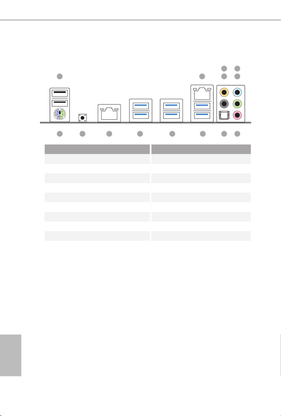
1.4 I/O Panel
No. No.Description Description
1 USB 2.0 Ports (USB12) 9 USB 3.0 Ports (USB3_56)
2 LAN RJ-45 Port USB 3.0 Ports (USB3_34)10
(Qualcomm® Atheros® AR8171)* (ASMedia ASM1074 hub)
3 Central / Bass (Orange) USB 3.0 Ports (USB3_12)11
4 Rear Speaker (Black) (ASMedia ASM1074 hub)
5 Line In (Light Blue) LAN RJ-45 Port12
6 Front Speaker (Lime)** (Intel® I218V)*
7 Clear CMOS SwitchMicrophone (Pink) 13
8 Optical SPDIF Out Port PS/2 Mouse/Keyboard Port14
1
14 78910111213
2 4
3
6
5

11
English
X99 OC Formula
* ere are two LEDs on each LAN port. Please refer to the table below for the LAN port LED indications.
Activity / Link LED Speed LED
Status StatusDescription Description
Of No Link Of 10Mbps connection
Blinking Data Activity Orange 100Mbps connection
On Link Green 1Gbps connection
** If you use a 2-channel speaker, please connect the speaker’s plug into “Front Speaker Jack”. See the table below
for connection details in accordance with the type of speaker you use.
Audio Output
Channels
Front Speaker
(No. 6)
Rear Speaker
(No. 4)
Central / Bass
(No. 3)
Line In
(No. 5)
2V -- -- --
4V V -- --
6V V V --
8V V V V
To enable Multi-Streaming, you need to connect a front panel audio cable to the front
panel audio header. Aer restarting your computer, you will nd the “Mixer” tool on your
system. Please select “Mixer ToolBox” , click “Enable playback multi-streaming”, and
click “ok”. Choose “2CH”, “4CH”, “6CH”, or “8CH” and then you are allowed to select
“Realtek HDA Primary output” to use the Rear Speaker, Central/Bass, and Front Speaker,
or select “Realtek HDA Audio 2nd output” to use the front panel audio.
ACT/LINK LED
SPEED LED
LAN Port

12
English
is is an EATX form factor motherboard. Before you install the motherboard,
study the conguration of your chassis to ensure that the motherboard ts into it.
Pre-installation Precautions
Take note of the following precautions before you install motherboard components
or change any motherboard settings.
Make sure to unplug the power cord before installing or removing the motherboard
components. Failure to do so may cause physical injuries and damages to motherboard
components.
In order to avoid damage from static electricity to the motherboard’s components,
NEVER place your motherboard directly on a carpet. Also remember to use a grounded
wrist strap or touch a safety grounded object before you handle the components.
Hold components by the edges and do not touch the ICs.
Whenever you uninstall any components, place them on a grounded anti-static pad or
in the bag that comes with the components.
When placing screws to secure the motherboard to the chassis, please do not over-
tighten the screws! Doing so may damage the motherboard.
Chapter 2 Installation

13
English
X99 OC Formula
2.1 Installing the CPU
CAUTION:
Please note that X99 platform is only compatible with the LGA 2011-3 socket, which is
incompatible with the LGA 2011 socket (for X79 platform).
1. Before you insert the -Pin CPU into the socket, please check if the is on 2011-3 PnP cap
the socket, if the CPU surface is unclean, or if there are any in the socket. Do bent pins
not force to insert the CPU into the socket if above situation is found. Otherwise, the CPU
will be seriously damaged .
2. Unplug all power cables before installing the CPU.
A
B
A
B
1
2

14
English
4
A
3
B
5

15
English
X99 OC Formula
Please save and replace the cover if the processor is removed. e cover must be placed if
you wish to return the motherboard for aer service.
6
A
B
8
B
7
A

16
English
2.2 Installing the CPU Fan and Heatsink
CPU_
FAN
1 2

17
English
X99 OC Formula
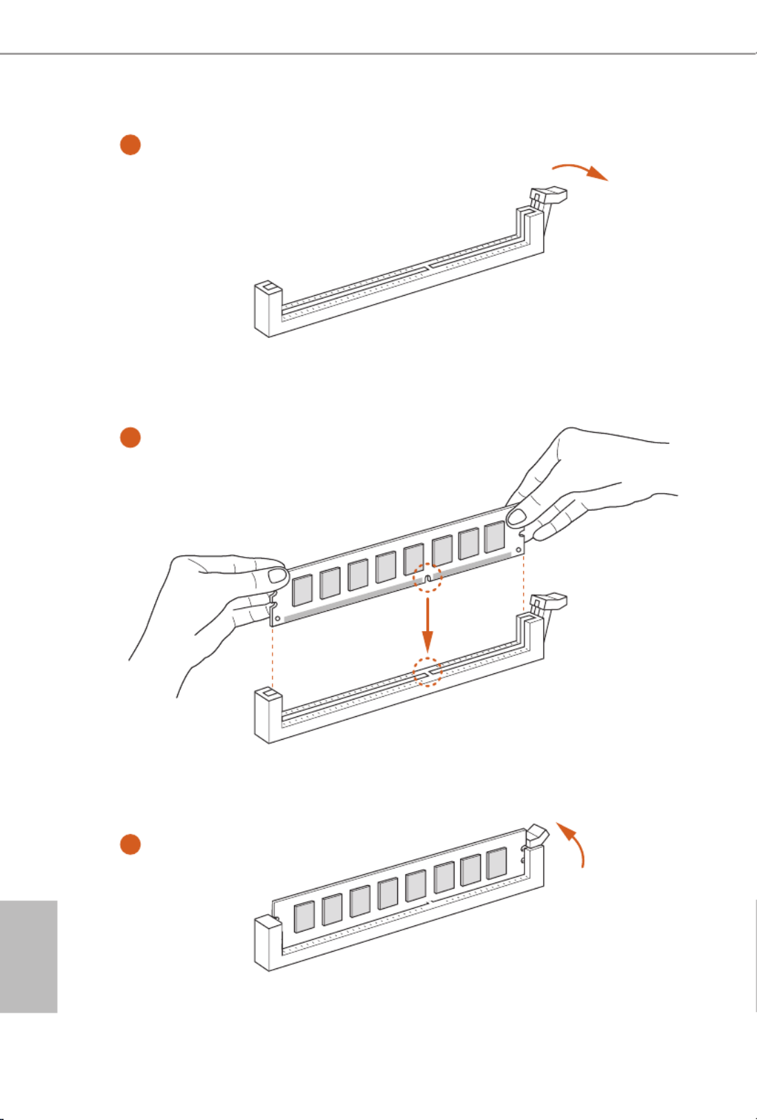
2.3 Installation of Memory Modules (DIMM)
is motherboard provides eight 288-pin DDR4 (Double Data Rate 4) DIMM slots, and
supports Quad Channel Memory Technology.
Quad Channel Memory Conguration
Priority 1 2
DDR4_A1 Populated Populated
DDR4_A2 Populated
DDR4_B1 Populated Populated
DDR4_B2 Populated
DDR4_C1 Populated Populated
DDR4_C2 Populated
DDR4_D1 Populated Populated
DDR4_D2 Populated
Due to Intel® CPU spec denition, please install the memory modules on DDR4_A1,
DDR4_B1, DDR4_C1 and DDR4_D1 for rst priority. If the four DDR4 DIMM slots
above are fully installed, and you want to use more than four memory modules, please
install the other memory modules from le to right (from DDR4_A2, DDR4_B2,
DDR4_D2 to DDR4_C2.)
If only two memory modules are installed in the DDR4 DIMM slots, then Dual
Channel Memory Technology is activated. If three memory modules are installed, then
Triple Channel Memory Technology is activated. If more than four memory modules
are installed in the DDR4 DIMM slots, then Quad Channel Memory Technology is
activated.
1. For quad channel conguration, you always need to install identical (the same brand,
speed, size and chip-type) DDR4 DIMM pairs.
2. It is not allowed to install a DDR, DDR2 or DDR3 memory module into a DDR4 slot;
otherwise, this motherboard and DIMM may be damaged.
3. e DIMM only ts in one correct orientation. It will cause permanent damage to the
motherboard and the DIMM if you force the DIMM into the slot at incorrect orientation.
18
English
1
2
3

19
English
X99 OC Formula
2.4 Expansion Slots (PCI Express Slots)
ere are 5 PCI Express slots and 1 mini-PCI Express slot on the motherboard.
mini-PCIe slots:
MINI_PCIE1 (mini-PCIe slot) is used for WiFi module.
PCIe slots:
PCIE1 (PCIe 3.0 x16 slot) is used for PCI Express x16 lane width graphics cards.
PCIE2 (PCIe 3.0 x16 slot) is used for PCI Express p25-x8 lane width graphics cards.
PCIE3 (PCIe 3.0 x16 slot) is used for PCI Express x8 lane width cards, such as
underbolt™ add-in card.
PCIE4 (PCIe 3.0 x16 slot) is used for PCI Express x16 lane width graphics cards.
PCIE5 (PCIe 3.0 x16 slot) is used for PCI Express x8 lane width graphics cards.
PCIe Slot Congurations (For CPU with 40 PCIe lanes)
PCIE1 PCIE2 PCIE4 PCIE5PCIE3
Single Graphics Card x16 N/A N/A N/A N/A
Two Graphics Cards in
CrossFireXTM or SLITM
Mode
x16 x16N/A N/A N/A
ree Graphics Cards in
3-Way CrossFireXTM Mode
or 3-Way SLITM Mode
x8 x8 N/A N/Ax16
Four Graphics Cards in
4-Way CrossFireXTM Mode
or 4-Way SLITM Mode
x8 x8 x8 x8N/A
For a better thermal environment, please connect a chassis fan to the motherboard’s chas-
sis fan connector (CHA_FAN1, CHA_FAN2 or CHA_FAN3) when using multiple graphics
cards.
Before installing an expansion card, please make sure that the power supply is switched o
or the power cord is unplugged. Please read the documentation of the expansion card and
make necessary hardware settings for the card before you start the installation.

20
English
PCIe Slot Congurations (For CPU with 28 PCIe lanes)
For a better thermal environment, please connect a chassis fan to the motherboard’s chas-
sis fan connector (CHA_FAN1, CHA_FAN2 or CHA_FAN3) when using multiple graphics
cards.
PCIE1 PCIE2 PCIE4 PCIE5PCIE3
Single Graphics Card x16 N/A N/A N/A N/A
Two Graphics Cards in
CrossFireX TM or SLITM
Mode
x16 N/A N/A N/Ax8
ree Graphics Cards in
3-Way CrossFireXTM Mode
or 3-Way SLITM Mode
x8 x8 x8N/A N/A
*4-Way CrossFireXTM and 4-Way SLITM are not supported for CPU with 28 PCIe lanes.

21
English
X99 OC Formula
2.5 Jumpers Setup
e illustration shows how jumpers are setup. When the jumper cap is placed on
the pins, the jumper is “Short”. If no jumper cap is placed on the pins, the jumper
is “Open”. e illustration shows a 3-pin jumper whose pin1 and pin2 are “Short”
when a jumper cap is placed on these 2 pins.
Clear CMOS Jumper
(CLRCMOS1)
(see p.7, No. 40)
CLRCMOS1 allows you to clear the data in CMOS. To clear and reset the system
parameters to default setup, please turn o the computer and unplug the power
cord from the power supply. Aer waiting for 15 seconds, use a jumper cap to
short pin2 and pin3 on CLRCMOS1 for 5 seconds. However, please do not clear
the CMOS right aer you update the BIOS. If you need to clear the CMOS when
you just nish updating the BIOS, you must boot up the system rst, and then shut
it down before you do the clear-CMOS action. Please be noted that the password,
date, time, and user default prole will be cleared only if the CMOS battery is
removed.
Clear CMOSDefault
e Clear CMOS Switch has the same function as the Clear CMOS jumper.

22
English
2.6 Onboard Headers and Connectors
System Panel Header
(9-pin PANEL1)
(see p.7, No. 32)
Connect the power
switch, reset switch and
system status indicator on
the chassis to this header
according to the pin
assignments below. Note
the positive and negative
pins before connecting
the cables.
Power LED Header
(3-pin PLED1)
(see p.7, No. 29)
Please connect the chassis
power LED to this header
to
indicate the system’s
power status.
GND
R #ESE T
PWRBTN#
PLED-
PLED+
GND
HDL ED-
HDL ED+
1
GND
PWRBTN (Power Switch):
Connect to the power switch on the chassis front panel. You may congure the way to turn
o your system using the power switch.
RESET (Reset Switch):
Connect to the reset switch on the chassis front panel. Press the reset switch to restart the
computer if the computer freezes and fails to perform a normal restart.
PLED (System Power LED):
Connect to the power status indicator on the chassis front panel. e LED is on when the
system is operating. e LED keeps blinking when the system is in S1/S3 sleep state. e
LED is o when the system is in S4 sleep state or powered o (S5).
HDLED (Hard Drive Activity LED):
Connect to the hard drive activity LED on the chassis front panel. e LED is on when the
hard drive is reading or writing data.
e front panel design may dier by chassis. A front panel module mainly consists of power
switch, reset switch, power LED, hard drive activity LED, speaker and etc. When connect-
ing your chassis front panel module to this header, make sure the wire assignments and the
pin assignments are matched correctly.
Onboard headers and connectors are NOT jumpers. Do NOT place jumper caps over these
headers and connectors. Placing jumper caps over the headers and connectors will cause
permanent damage to the motherboard.
1
PLED+
PLED+
PLED-

24
English
Front Panel Audio Header
(9-pin HD_AUDIO1)
(see p.7, No. 44)
is header is for
connecting audio devices
to the front audio panel.
Chassis Speaker Header
(4-pin SPEAKER1)
(see p.7, No. 31)
Please connect the chassis
speaker to this header.
Chassis and Power Fan
Connectors
(4-pin CHA_FAN1)
(see p.7, No. 39)
(3-pin CHA_FAN2)
(see p.7, No. 35)
(3-pin CHA_FAN3)
(see p.7, No. 20)
(3-pin PWR_FAN1)
(see p.7, No. 45)
Please connect fan cables
to the fan connectors and
match the black wire to
the ground pin. CHA_
FAN fan speed can be
controlled through UEFI
or Formula Drive.
J _ S E N S E
O U T 2 _ L
1
MIC_RET
PRESENCE#
GND
OUT2_R
MIC2_R
MIC2_L
OUT_RET
1
+5V
DUMMY
DUMMY
SPE AKE R
GND
+12V
CHA_FAN_SPEED
FAN _ S PEED _CONTROL
GND
F AN _V OL T AG
E
CHA_FAN_SP EED
1. High Denition Audio supports Jack Sensing, but the panel wire on the chassis must sup-
port HDA to function correctly. Please follow the instructions in our manual and chassis
manual to install your system.
2. If you use an AC’97 audio panel, please install it to the front panel audio header by the
steps below:
A. Connect Mic_IN (MIC) to MIC2_L.
B. Connect Audio_R (RIN) to OUT2_R and Audio_L (LIN) to OUT2_L.
C. Connect Ground (GND) to Ground (GND).
D. MIC_RET and OUT_RET are for the HD audio panel only. You don’t need to connect
them for the AC’97 audio panel.
E. To activate the front mic, go to the “FrontMic” Tab in the Realtek Control panel and
adjust “Recording Volume”.
GND
FAN_VOLTAGE
CHA
_
FAN
_
SPEED

26
English
underbolt AIC
Connector
(5-pin TBT1)
(see p.7, No. 43)
Please connect a underbolt™
add-in card (AIC) to this
connector via the GPIO cable.
*Please install the underbolt™
AIC card to PCIE3 (default
slot).
Serial Port Header
(9-pin COM1)
(see p.7, No. 41)
is COM1 header
supports a serial port
module.
TPM Header
(17-pin TPMS1)
(see p.7, No. 36)
is connector supports Trusted
Platform Module (TPM) system,
which can securely store keys,
digital certicates, passwords,
and data. A TPM system also
helps enhance network security,
protects digital identities, and
ensures platform integrity.
1
GN D
SMB_DATA_MAIN
LAD2
LAD1
GN D
S_PWRDWN #
SERIRQ #
GN D
P CICL K
P CIR ST #
LAD3
+ 3 V
LAD0
+3VS B
GN D
FRAM E SMB_CLK_MAIN
CC T S# 1
RR T S# 1
DD SR # 1
DD T R# 1
RRXD1
GND
TT XD1
DD CD # 1
1
RR I# 1

27
English
X99 OC Formula
I.5V PCH
1.05V CPU
VCCM
CORE
VCC_IN
GND
1.05V PCH
1
V-ProbeTM
(7-pin VOL_
CON1)
(see p.7, No. 15)
Users are able to measure
onboard components
voltage.
PIN1:
1.5V PCH:
PCH PLL Voltage
PIN2:
1.05V PCH:
PCH Voltage
PIN3:
1.05V CPU:
CPU I/O Voltage (CPU_
V10)
PIN4:
VCCM:
DRAM Voltage
PIN5:
CORE3
:
3rd CPU CORE
voltage (only works with
8-cores CPU)
PIN6:
VCC_IN:
CPU Input Voltage
PIN7:
GND

28
English
2.7 Smart Switches
e motherboard has eleven smart switches: Power Switch, Reset Switch, Clear
CMOS Switch, Rapid OC Buttons, Menu Button, PCIe ON/OFF Switch, Slow Mode
Switch, BIOS Selection Switch, LN2 Mode Switch and Direct Key Button.
Power Switch
(PWR)
(see p.7, No. 33)
Power Switch allows users to
quickly turn on/o the system.
Reset Switch
(RST)
(see p.7 No. 34)
Reset Switch allows users to
quickly reset the system.
Clear CMOS Switch
(CLRCBTN1)
(see p.10, No. 13)
Clear CMOS Switch allows
users to quickly clear the
CMOS values.
+ / - Rapid OC But-
tons
(MINUS: see p.7, No.
10)
(PLUS: see p.7, No. 9)
+ / - Rapid OC Buttons allow
users to quickly and easily
adjust OC frequency in Rapid
OC.
Menu Button
(MENU: see p.7, No.
11)
MENU Button allow users to
quickly toogle among Date/
Time, Temperature, and Volt-
age information.
Power
Reset
is function is workable only when you power o your computer and unplug the power
supply.
+
U
is overclocking behavior depends on the system conguration, such as memory capabil-
ity, thermal solution, etc. Overclocking may aect your system stability, or even cause dam-
age to the components and devices. We are not responsible for possible damage caused by
overclocking.
29
English
X99 OC Formula
PCIe ON/OFF
Switch
(PCIE_SWITCH)
(see p.7, No. 12)
PCIe ON/OFF Switch allows
you to enable and disable the
corresponding PCIE x16 slots.
When one of the installed
PCIE x16 cards is out of order,
you can use PCIe ON/OFF
Switch to nd out the faulty
one just with a single click
without removing the cards.
Slow Mode Switch
(SLOWMODE)
(see p.7, No. 14)
If Slow Mode is on, the
processor runs at lowest fre-
quency.
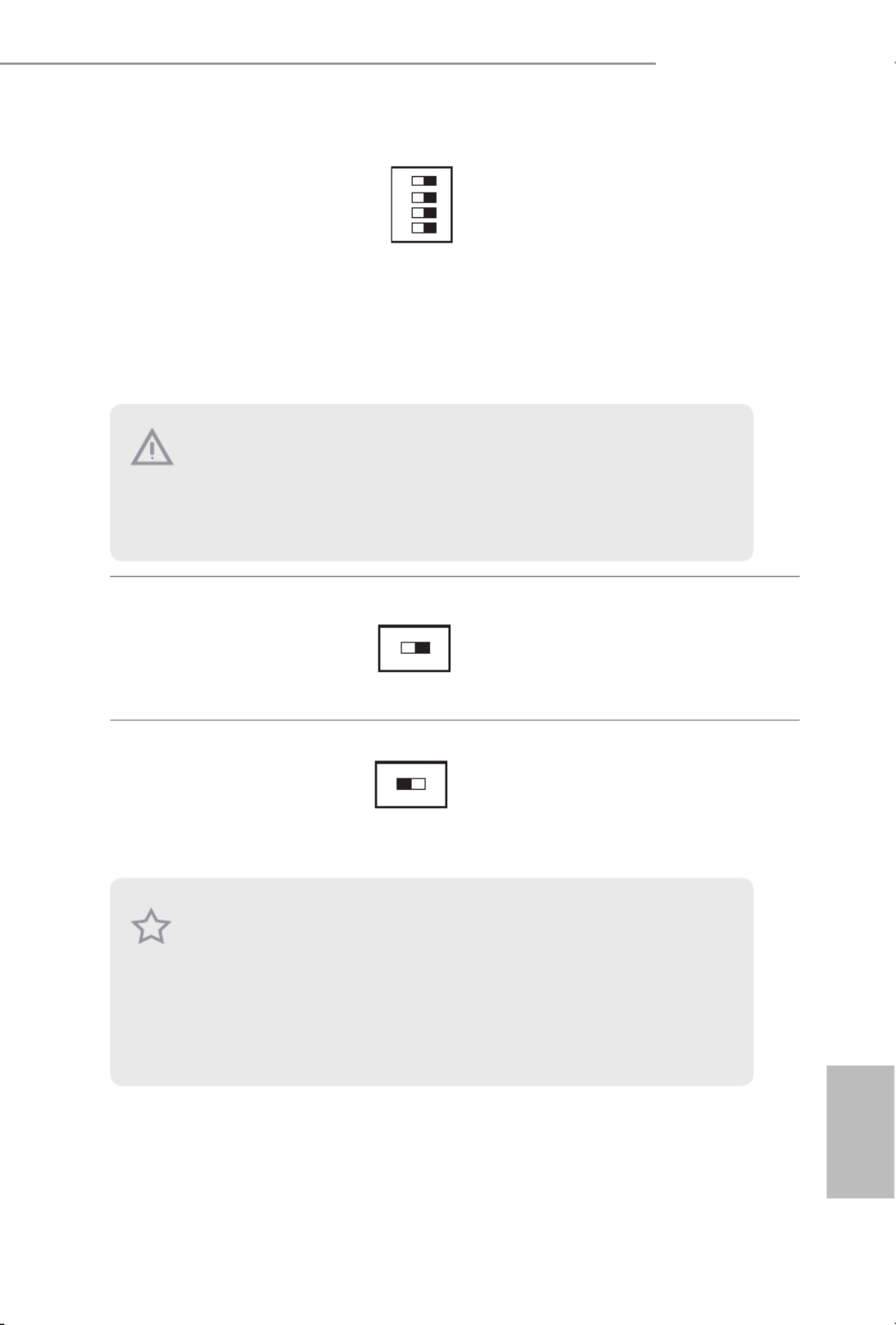
BIOS Selection
Switch
(BIOS_SEL1)
(see p.7, No. 28)
BIOS Selection Switch allows
the system to boot from either
BIOS A or BIOS B.
ON
1234
1: PCIE1
2: PCIE2
3: PCIE4
4: PCIE5
ON
OFF
A B
is motherboard has two BIOS chips, a primary BIOS (BIOS_A) and a backup BIOS (BIOS_
B), which enhances the safety and stability of your system. Normally, the system will work
on the primary BIOS. However, if the primary BIOS is corrupted or damaged, just ip the
BIOS Selection Switch to “B”, then the backup BIOS will take over on the next system boot.
Aer that, use “Secure Backup UEFI” in the UEFI Setup Utility to duplicate a working copy
of the BIOS les to the primary BIOS to ensure normal system operation. For safety issues,
users are not able to update the backup BIOS manually. Users may refer to the BIOS LEDs
(BIOS_A_LED or BIOS_B_LED) to identify which BIOS is currently activated.
1. Make sure that you power o the system before changing the switch.
2. When you turn o PCIe ON/OFF switch, your PCIE card could be burnt if it was poorly
designed. For more information about your card’s specications please contact the card’s
vendor.
3. PCIe ON/OFF switch is for debug only. If you do not want to use your PCIE card, please
remove it from the motherboard.

30
English
LN2 Mode Switch
(LN2MODE)
(see p.7, No. 13)
e LN2 mode aids in
eliminating the cold-boot bug
issues in processors during
extreme overclocking with
Liquid Nitrogen.
Direct Key Button
(DIRKEY1)
(see p.7, No. 30)
Direct Key Button allows
users to turn on the system
and directly enter the UEFI
setup screen.
ON
OFF

32
English
b4 Problem related to USB devices. Please try removing all
USB devices.
b7 Problem related to memory. Please re-install the CPU and
memory then clear CMOS. If the problem still exists, please
install only one memory module or try using other memory
modules.
d6 e VGA could not be recognized. Please clear CMOS and
try re-installing the VGA card. If the problem still exists,
please try installing the VGA card in other slots or use other
VGA cards.
d7 e Keyboard and mouse could not be recognized. Please
try re-installing the keyboard and mouse.
d8 Invalid Password.
FF Please check if the CPU is installed correctly and then clear
CMOS.

33
English
X99 OC Formula
2.9 Post Status Checker
Post Status Checker (PSC) diagnoses the computer when users power on the
machine. It emits a red light to indicate whether the CPU, memory, VGA or stor-
age is dysfunctional. e lights go o if the four mentioned above are functioning
normally.

34
English
2.10 SLI
TM
, 3-Way SLI
TM
, 4-Way SLI
TM
and Quad SLI
TM
Operation
Guide
is motherboard supports NVIDIA ®
SLI
TM , 3-way SLI
TM, 4-way SLI
TM and Quad
SLITM (Scalable Link Interface) technology that allows you to install up to four
identical PCI Express x16 graphics cards. Currently, NVIDIA
®
SLI
TM and Quad
SLITM technology supports Windows ®
7 / 7 64-bit / 8 / 8 64-bit / 8.1 / 8.1 64-bit OS.
*If you install CPU with 28 lanes, 4-Way SLI
TM is not supported.
2.10.1 Installing Two SLI
TM
-Ready Graphics Cards
Step 1
Insert one graphics card into PCIE1 slot
and the other graphics card to PCIE4 slot.
Make sure that the cards are properly
seated on the slots.
Step 2
If required, connect the auxiliary power
source to the PCI Express graphics cards.
Requirements
1. You should only use identical SLI
TM-ready graphics cards that are NVIDIA
®
certied.
2. Make sure that your graphics card driver supports NVIDIA
®
SLI
TM technology. Download
the drivers from the NVIDIA
®
website: www.nvidia.com
3. Make sure that your power supply unit (PSU) can provide at least the minimum power
your system requires. It is recommended to use a NVIDIA
®
certied PSU. Please refer to
the NVIDIA
®
website for details.

35
English
X99 OC Formula
Step 3
Align and insert the ASRock Flexible SLI
Bridge Connector Cable to the goldngers
on each graphics card. Make sure the
ASRock Flexible SLI Bridge Connector
Cable is rmly in place.
Step 4
Connect a VGA cable or a DVI cable to the
monitor connector or the DVI connector of
the graphics card that is inserted to PCIE1
slot.
ASRock Flexible SLI Bridge Connector Cable
Multi-GPU SLI
Video Link Card
M
u
l
t
i
-
G
P
U
S
L
I
V
i
d
e
o
L
i
n
k
C
a
r
d
M
ulti- G
PU
SLI
Vi
deo
Link
C
ard

36
English
2.10.2 Installing Three SLI
TM
-Ready Graphics Cards
Step 1
Insert one graphics card into PCIE1 slot,
another graphics card to PCIE2 slot, and
the other graphics card to PCIE4 slot.
Make sure that the cards are properly
seated on the slots.
Step 2
Connect the auxiliary power source to the
PCI Express graphics card. Please make
sure that both power connectors on the
PCI Express graphics card are connected.
Repeat this step on the three graphics
cards.
Step 3
Align and insert the three ASRock
Flexible SLI Bridge Connector Cables to
the goldngers on each graphics card, as
illustrated in the le gure. Make sure the
ASRock Flexible SLI Bridge Connector
Cables are rmly installed.
Multi-G
Multi-GPU SLI
Video Link Card
M
ulti-G PU SLI
Video Link C
ard
ASRock Flexible SLI Bridge
Connector Cables (2 x 10 cm, 1 x 14 cm)
Multi-GPU SLI
Video Link Card
Multi-GPU SLI
Video Link Card
Multi-GPU SLI
Video Link Card
37
English
X99 OC Formula
Step 4
Connect a VGA cable or a DVI cable to the
monitor connector or the DVI connector of
the graphics card that is inserted to PCIE1
slot.
Step 4
Connect a VGA cable or a DVI cable to the
monitor connector or the DVI connector of
the graphics card that is inserted to PCIE1
slot.
Multi-G
Multi-GPU SLI
Video Link Card
M
ulti-G PU SLI
Video Link C
ard

38
English
2.10.3 Installing Four SLI
TM
-Ready Graphics Cards
Step 1
Insert one graphics card into the PCIE1
slot, another graphics card into the PCIE2
slot, the third graphics card into the PCIE4
slot and the last graphics card into the
PCIE5 slot. Make sure that the cards are
properly seated on the slots.
Step 2
Connect the auxiliary power source to the
PCI Express graphics card. Please make
sure that both power connectors on the
PCI Express graphics card are connected.
Repeat this step on the three graphics
cards.
Step 3
Align and insert an ASRock Flexible SLI
Bridge Connector Cable (10 cm) to the
goldngers of the rst and second graphics
card. Install the second ASRock Flexible
SLI Bridge Connector Cable (10 cm) to
the goldngers of the third and fourth
graphics card. Connect the second and
the fourth graphics card with the ASRock
Flexible SLI Bridge Connector Cable
(14 cm). Make sure the ASRock Flexible
SLI Bridge Connector Cables are rmly
installed.
Multi-GPU SLI
Video Link Card
Multi-GPU SLI
Video Link Card
Multi-GPU SLI
Video Link Card
ASRock Flexible SLI Bridge
Connector Cables (2 x 10 cm, 1 x 14 cm)
Multi-GPU SLI
Video Link Card
Multi-GPU SLI
Video Link Card
Multi-GPU SLI
Video Link Card
41
English
X99 OC Formula
2.11 CrossFireX
TM
, 3-Way CrossFireX
TM
, 4-Way CrossFireX
TM
and Quad CrossFireXTM
Operation Guide
is motherboard supports CrossFireX TM, 3-way CrossFireX
TM, 4-way CrossFireX
TM
and Quad CrossFireXTM that allows you to install up to four identical PCI
Express p47-x16 graphics cards. Currently CrossFireX
TM, 3-way CrossFireX
TM, 4-way
CrossFireXTM and Quad CrossFireXTM are supported with Windows ®
7 / 7 64-bit / 8
/ 8 64-bit / 8.1 / 8.1 64-bit OS.
*If you install CPU with 28 lanes, 4-Way CrossFireX
TM is not supported.
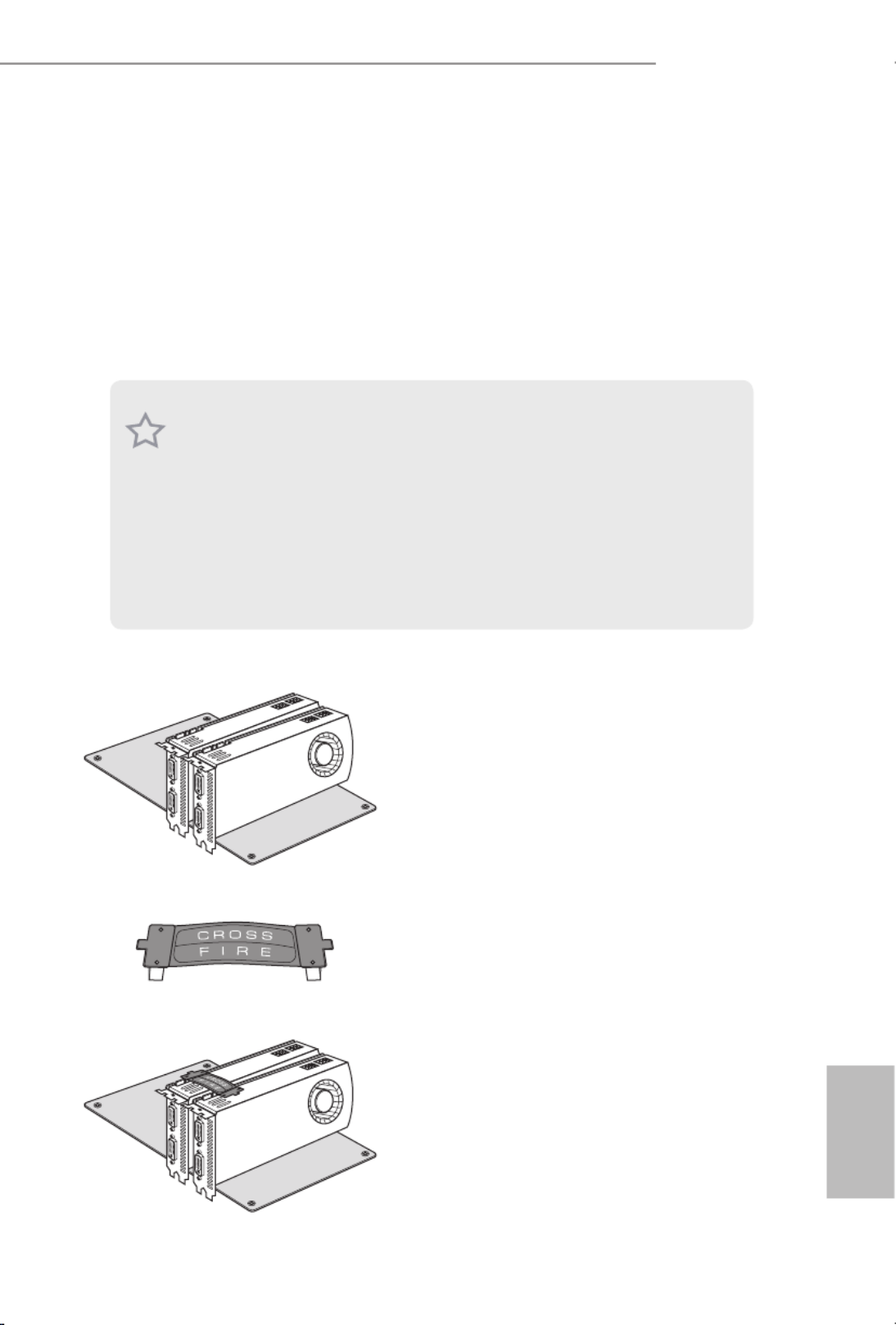
2.11.1 Installing Two CrossFireX
TM
-Ready Graphics Cards
Step 1
Insert one graphics card into PCIE1 slot
and the other graphics card to PCIE4 slot.
Make sure that the cards are properly
seated on the slots.
Step 2
Connect two graphics cards by installing
a CrossFire Bridge on the CrossFire Bridge
Interconnects on the top of the graphics
cards. (e CrossFire Bridge is provided
with the graphics card you purchase, not
bundled with this motherboard. Please
refer to your graphics card vendor for
details.)
1. You should only use identical CrossFireX
TM
-ready graphics cards that are AMD certied.
2. Make sure that your graphics card driver supports AMD CrossFireX
TM technology.
Download the drivers from the AMD’s website: www.amd.com
3. Make sure that your power supply unit (PSU) can provide at least the minimum power
your system requires. It is recommended to use a AMD certied PSU. Please refer to the
AMD’s website for details.
4. If you pair a 12-pipe CrossFireX
TM
Edition card with a 16-pipe card, both cards will oper-
ate as 12-pipe cards while in CrossFireX
TM mode.
5. Dierent CrossFireX
TM cards may require dierent methods to enable CrossFireX
TM .
Please refer to AMD graphics card manuals for detailed installation guide.
CrossFire Bridge
42
English
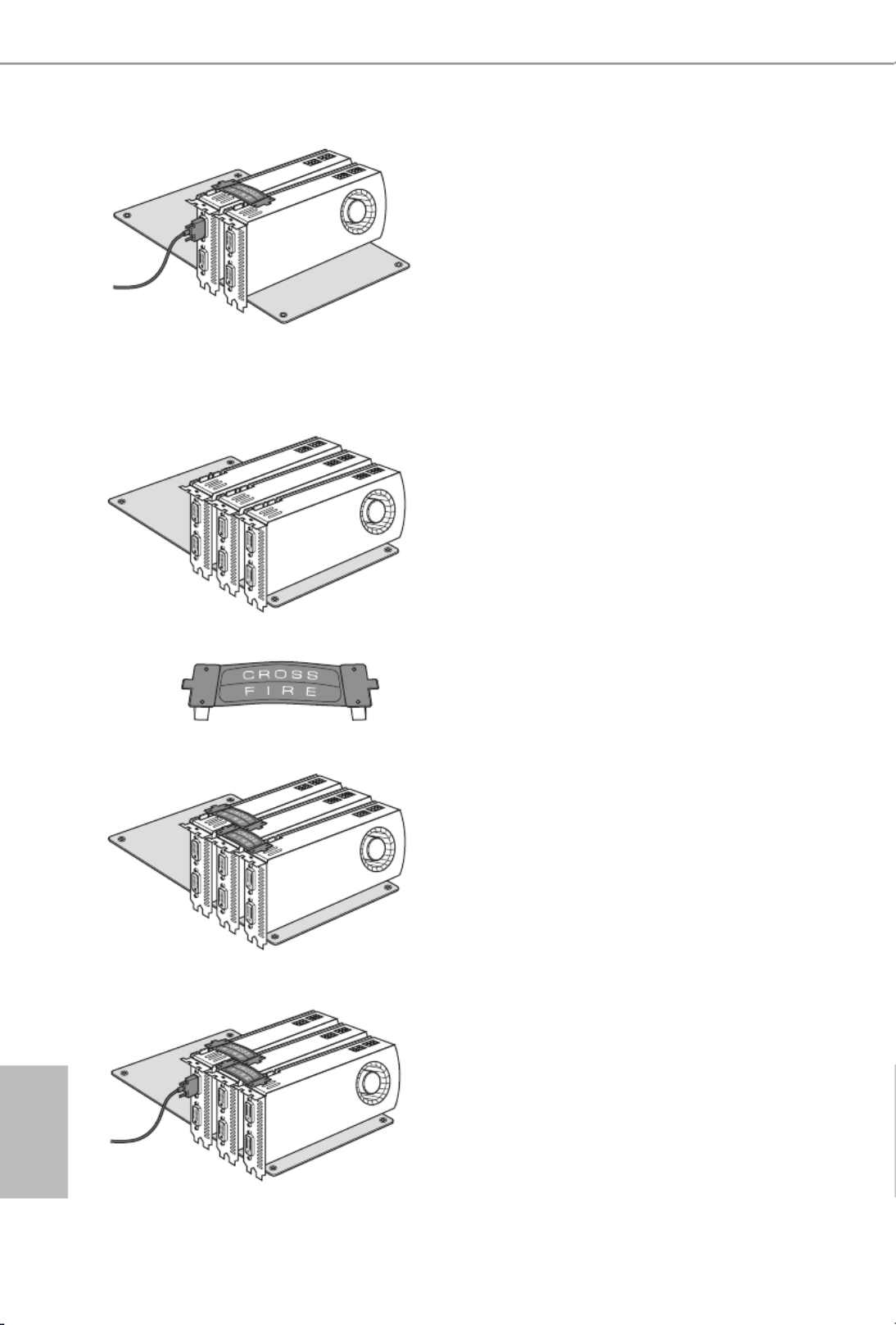
2.11.2 Installing Three CrossFireX
TM
-Ready Graphics Cards
Step 3
Connect a VGA cable or a DVI cable to the
monitor connector or the DVI connec-
tor of the graphics card that is inserted to
PCIE1 slot.
Step 1
Insert one graphics card into PCIE1 slot,
another graphics card to PCIE2 slot, and
the other graphics card to PCIE4 slot.
Make sure that the cards are properly
seated on the slots.
Step 2
Use one CrossFire Bridge to connect
the graphics cards on PCIE1 and PCIE2
slots, and use the other CrossFire Bridge
to connect the graphics cards on PCIE2
and PCIE4 slots. (e CrossFire Bridge
is provided with the graphics card
you purchase, not bundled with this
motherboard. Please refer to your graphics
card vendor for details.)
Step 3
Connect a VGA cable or a DVI cable to the
monitor connector or the DVI connec-
tor of the graphics card that is inserted to
PCIE1 slot.
CrossFire Bridge

43
English
X99 OC Formula
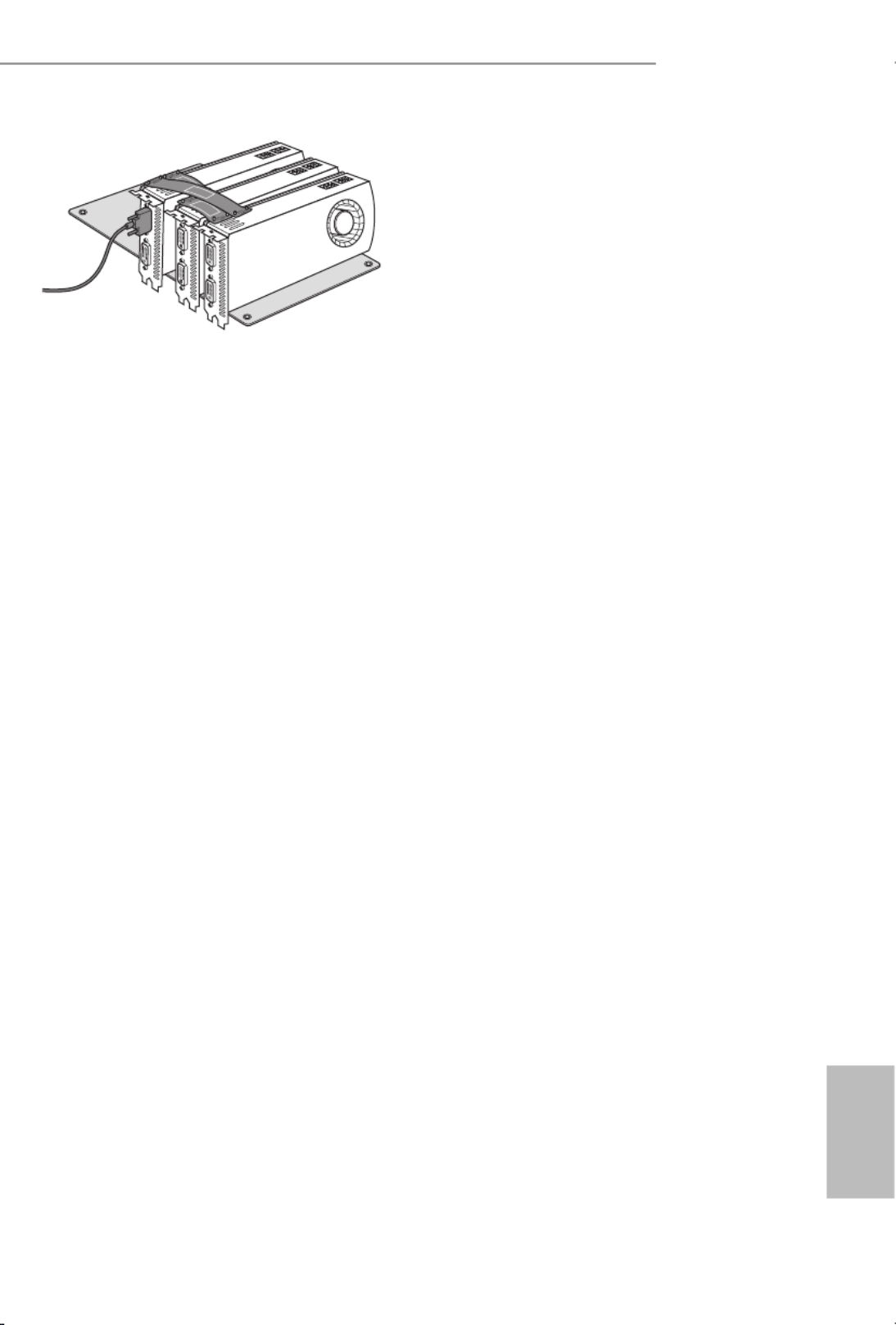
2.11.3 Installing Four CrossFireX
TM
-Ready Graphics Cards
Step 1
Insert one graphics card into PCIE1 slot,
another graphics card into PCIE2 slot, the
third graphics card into PCIE4 slot and the
last graphics card into PCIE5 slot. Make
sure that the cards are properly seated on
the slots.
Step 2
Use one CrossFireTM Bridge to connect
the graphics cards on PCIE1 and PCIE2
slots, another CrossFireTM Bridge to
connect the graphics cards on PCIE2 and
PCIE4 slots, and use the third CrossFireTM
Bridge to connect the graphics cards on
PCIE4 and PCIE5 slots. (e CrossFire TM
Bridge is provided with the graphics
card you purchase, not bundled with this
motherboard. Please refer to your graphics
card vendor for details.)
Step 3
Connect a VGA cable or a DVI cable to the
monitor connector or the DVI connec-
tor of the graphics card that is inserted to
PCIE1 slot.
CrossFire Bridge

44
English
Step 1
Power on your computer and boot into OS.
Step 2
Remove the AMD drivers if you have any VGA drivers installed in your system.
Step 3
Install the required drivers and CATALYST Control Center then restart your
computer. Please check AMD’s website for details.
2.11.4 Driver Installation and Setup
Step 4
Double-click the AMD Catalyst Control
Center icon in the Windows ®
system tray.
Step 5
In the le pane, click and Performance
then AMD CrossFireX TM. en select
Enable AMD CrossFireX and click .Apply
Select the GPU number according to your
graphics card and click .Apply
AMD Catalyst Control Center
e Catalyst Uninstaller is an optional download. We recommend using this utility to un-
install any previously installed Catalyst drivers prior to installation. Please check AMD’s
website for AMD driver updates.

45
English
X99 OC Formula
2.12 M.2_SSD (NGFF) Module Installation Guide
e M.2 (M2_1), also known as the Next Generation Form Factor (NGFF), is a small size
and versatile card edge connector that aims to replace mPCIe and mSATA. e Ultra M.2
Socket (ULTRA_M2) can accommodate a M.2 PCI Express module up to Gen3 p51-x4 (32 Gb/s).
e M.2_SSD(NGFF) Socket 3 (M2_1) can accommodate either a M.2 SATA3 6.0 Gb/s
module or a M.2 PCI Express module up to Gen 2 p51-x4 (20 Gb/s).
Please be noted that the M.2 Socket (M2_1) is shared with the S_SATA3_3 connector.
If you install a M.2 SATA module to the M.2 Socket (M2_1), the internal S_SATA3_3
will not function. If you install a M.2 PCI Express module to the M.2 Socket (M2_1), the
internal S_SATA3_3 will still function.
* If Ultra M.2 PCI Express module is installed, PCIE3 slot will be disabled.
* When you overclock the BCLK frequency, it is recommended that you install the M.2 PCI
Express module to the M.2 Socket (M2_1).
Installing the M.2_SSD (NGFF) Module
Step 1
Prepare a M.2_SSD (NGFF) module
and the screw.
3
2
4
5
BCDE A
1
Step 2
Depending on the PCB type and
length of your M.2_SSD (NGFF)
module, nd the corresponding nut
location to be used.
No. 1 2 3 4 5
Nut Location A B C D E
PCB Length 3cm 4.2cm 6cm 8cm 11cm
Module Type Type2230 Type 2242 Type2260 Type 2280 Type 22110

46
English
BCDE A
Step 3
Move the stando based on the
module type and length.
e stando is placed at the nut
location D by default. Skip Step 3
and 4 and go straight to Step 5 if you
are going to use the default nut.
Otherwise, release the stando by
hand.
BCDE A
Step 4
Peel o the yellow protective lm on
the nut to be used. Hand tighten the
stando into the desired nut location
on the motherboard.
BC A
ABCDE
Step 5
Align and gently insert the M.2
(NGFF) SSD module into the M.2
slot. Please be aware that the M.2
(NGFF) SSD module only ts in one
orientation.
DE
Step 6
Tighten the screw with a screwdriver
to secure the module into place.
Please do not overtighten the screw
as this might damage the module.

47
English
X99 OC Formula
M.2_SSD (NGFF) Module Support List
For the latest updates of M.2_SSD (NFGG) module support list, please visit our website for
details: http://www.asrock.com
PCIe Interface SATA Interface
Plextor PX-G512M6e ADATA AXNS381E-128GM-B
Plextor PX-G256M6e ADATA AXNS381E-256GM-B
SanDisk SD6PP4M-128G Crucial CT120M500SSD4/120G
SanDisk SD6PP4M-256G Crucial CT240M500SSD4/240G
Samsung XP941-512G (MZHPU512HCGL) Intel SSDSCKGW080A401/80G
Kingston RBU-SM2280S3/120G
48
English
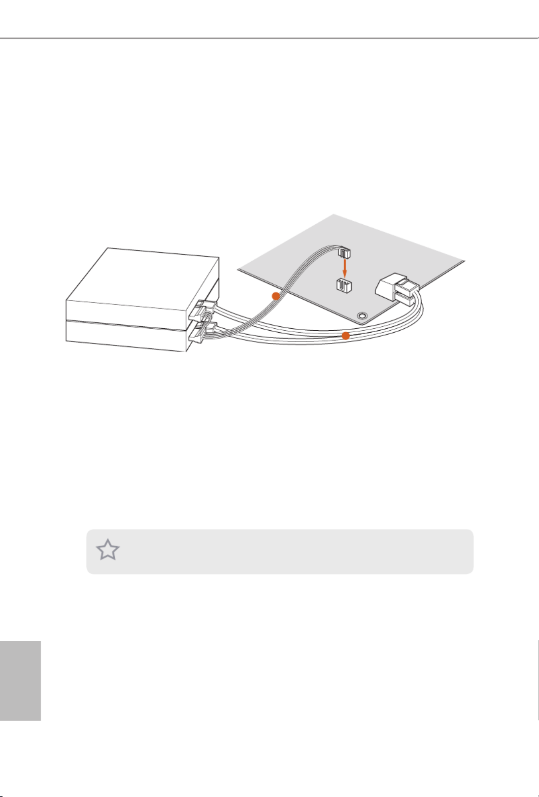
2.13 HDD Saver Cable Installation Guide
The HDD Saver Connector on this motherboard allows you to switch on and off the
connected HDDs via soware when needed. is design secures more privacy, saves more
energy, and extends the HDDs' lifespans. Please follow the steps below to install the HDD
Saver Cable.
Connection Diagram
*e diagram shown here is for reference only.
1. Connect one end of the HDD Saver Cable to the HDD Saver Connector (SATA_
PWR_1) placed near the SATA ports. en connect the SATA power connector(s) to
your SATA HDD(s).
* e HDD Saver Connector supports up to two SATA HDDs.
2. Connect one end of the SATA data cable to a SATA port on the motherboard. en
connect the other end to your SATA HDD(s).
2
1
HDD Saver Cable
SATA data cable
For the soware conguration, please refer to the section 3.2 “Formula Drive” in this user
manual.

49
English
X99 OC Formula
Chapter 3 Software and Utilities Operation
3.1 Installing Drivers
e Support CD that comes with the motherboard contains necessary drivers and
useful utilities that enhance the motherboard’s features.
Running The Support CD
To begin using the support CD, insert the CD into your CD-ROM drive. e CD
automatically displays the Main Menu if “AUTORUN” is enabled in your computer.
If the Main Menu does not appear automatically, locate and double click on the le
“ASRSETUP.EXE” in the Support CD to display the menu.
Drivers Menu
e drivers compatible to your system will be auto-detected and listed on the
support CD driver page. Please click Install All or follow the order from top to
bottom to install those required drivers. erefore, the drivers you install can work
properly.
Utilities Menu
e Utilities Menu shows the application soware that the motherboard supports.
Click on a specic item then follow the installation wizard to install it.
To improve Windows 7 compatibility, please download and install the following hot x
provided by Microso.
“KB2720599”: http://support.microso.com/kb/2720599
50
English
3.2 Formula Drive
Formula Drive is ASRock’s multi purpose soware suite with a new interface, more
new features and improved utilities, including XFast RAM, Dehumidier, Good
Night LED, FAN-Tastic Tuning, OC Tweaker and a whole lot more.
3.2.1 Installing Formula Drive
When you install the all-in-one driver to your system from ASRock’s support
CD, Formula Drive will be auto-installed as well. Aer the installation, you will
nd the icon “Formula Drive“ on your desktop. Double-click the “Formula Drive“
icon, Formula Drive main menu will pop up.
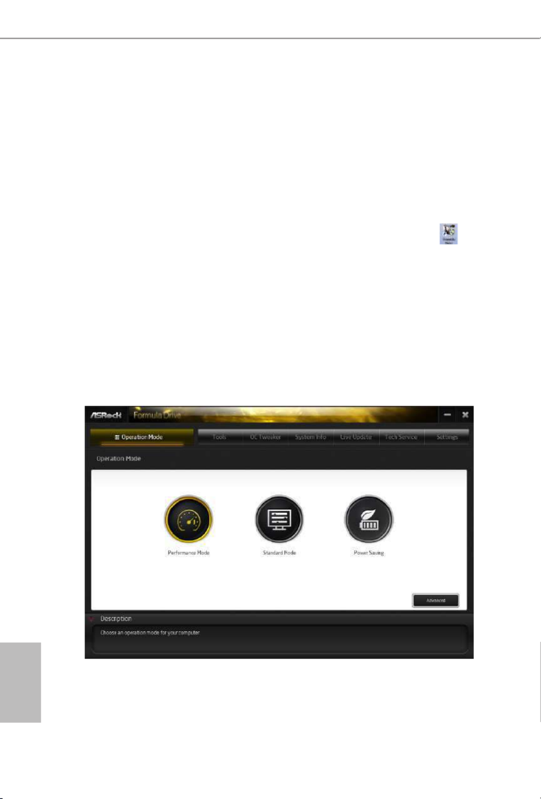
3.2.2 Using Formula Drive
ere are six sections in Formula Drive main menu: Operation Mode, Tools, OC
Tweaker, System Info, Live Update, Tech Service and Settings.
Operation Mode
Choose an operation mode for your computer.

51
English
X99 OC Formula
Tools
Various tools and utilities.
XFast RAM
Boost the system’s performance and extend the HDD’s or SDD’s lifespan! Create a
hidden partition, then assign which les should be stored in the RAM drive.
XFast LAN
Boost the speed of your internet connection! Select a specic mode for making the
designated program's priority highest.
Fast Boot
Fast Boot minimizes your computer's boot time. Please note that Ultra Fast mode
is only supported by Windows 8.1/8 and the VBIOS must support UEFI GOP if you
are using an external graphics card.
OMG
Schedule the starting and ending hours of Internet access granted to other users.
Place X marks on the time table to disable the Internet.
Good Night LED
Switch o the Power/HDD LEDs when the system is on, and automatically switch
o the Power and Keyboard LEDs when the system enters into Standby/Hibernation
mode.

52
English
FAN-Tastic Tuning
Congure up to ve dierent fan speeds using the graph. e fans will automatically
shi to the next speed level when the assigned temperature is met.
Dehumidier
Prevent motherboard damages due to dampness. Enable this function and
congure the period of time until the computer powers on, and the duration of the
dehumidifying process.
USB Key
Plug in the USB Key and let your computer log in to windows automatically!
OC DNA
OC DNA is an unique soware which helps to save your OC settings as a prole.
en you can send this OC setting prole to the friends.
HDD Saver
A quick-and-easy way to power up and down the drive on demand. Use a
customized hotkey (Ctrl + Alt + S, by default) or simply slide to turn on and o
up to two internal SATA HDDs connected to the power supply connector. Also a
password can be set to change HDD power mode for more privacy and safety.
Disk Health Report
Disk Health Report is a hard disk health monitoring utility that displays detailed
HDD information, such as hard disk model, serial number, rmware, power on
count, power on hours, S.M.A.R.T. values, current temperature, etc. HDD, SSD
and optical disk drives are all supported. e health status block displays Good
(in green color), Caution (in yellow color) or Bad (in red color). Click on the health
status icon to congure settings for an alert to be triggered.

53
English
X99 OC Formula
OC Tweaker
Congurations for overclocking the system.
System Info
View information about the system.

54
English
Multi Thermal Sensor
It provides users the temperature of various parts of the motherboard graphically,
so that users may precisely keep track and control of the temperature of each parts
of their motherboard when overclocking.
System Browser
System Browser shows the overview of your current PC and the devices connected.
Hardware Monitor
Shows the major readings of your system.
Live Update
Check for newer versions of BIOS or drivers.

55
English
X99 OC Formula
Tech Service
Contact Tech Service if you have problems with your computer. Please leave your
contact information along with details of the problem.
Settings
Congure ASRock Formula Drive. Click to select "Auto run at Windows Startup" if
you want Formula Drive to be launched when you start up the Windows operating
system.

56
English
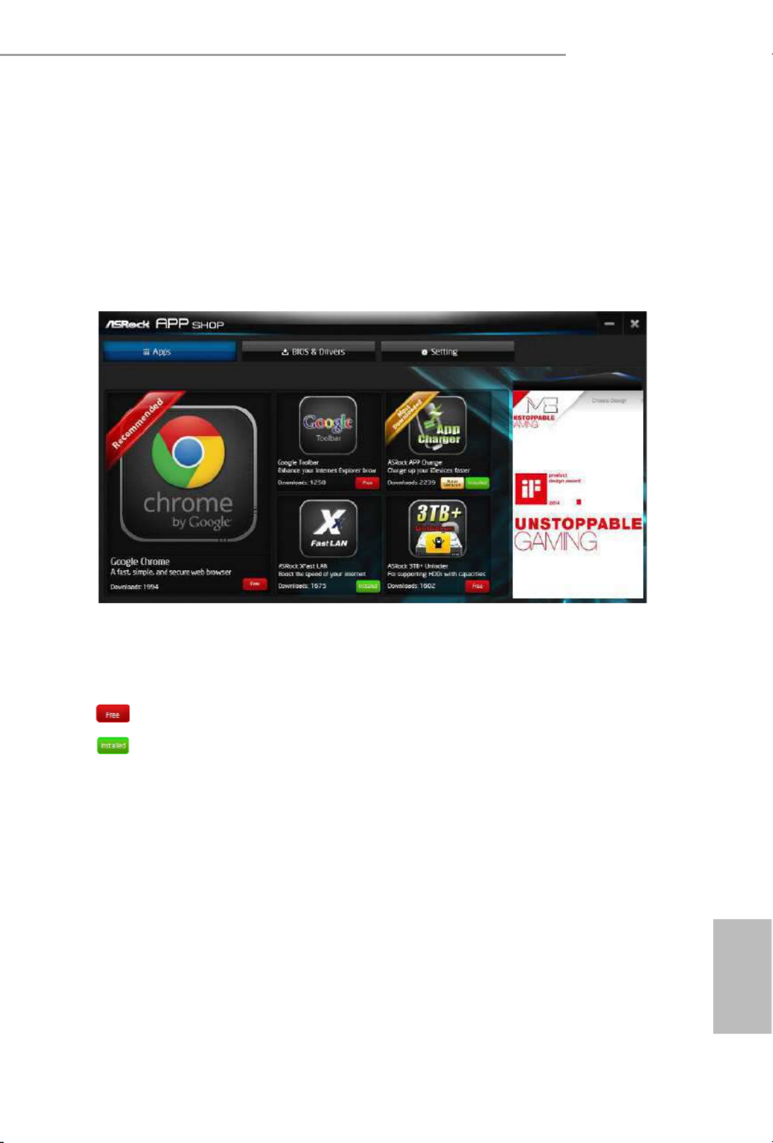
3.3 ASRock APP Shop
e ASRock APP Shop is an online store for purchasing and downloading soware
applications for your ASRock computer. You can install various apps and support
utilities quickly and easily, and optimize your system and keep your motherboard
up to date simply with a few clicks.
Double-click on your desktop to access ASRock APP Shop utility.
*You need to be connected to the Internet to download apps from the ASRock APP Shop.
3.3.1 UI Overview
Category Panel: e category panel contains several category tabs or buttons that
when selected the information panel below displays the relative information.
Information Panel: e information panel in the center displays data about the
currently selected category and allows users to perform job-related tasks.
Hot News: e hot news section displays the various latest news. Click on the image
to visit the website of the selected news and know more.
Information Panel
Hot News
Category Panel
57
English
X99 OC Formula
3.3.2 Apps
When the "Apps" tab is selected, you will see all the available apps on screen for you
to download.
Installing an App
Step 1
Find the app you want to install.
e most recommended app appears on the le side of the screen. e other various
apps are shown on the right. Please scroll up and down to see more apps listed.
You can check the price of the app and whether you have already intalled it or not.
- e red icon displays the price or "Free" if the app is free of charge.
- e green "Installed" icon means the app is installed on your computer.
Step 2
Click on the app icon to see more details about the selected app.

64
English
Control lets you congure what a click on the start button or a press on the
Windows key does.
Desktop
Desktop allows you to disable the hot corners when you are working on the desktop.
It also lets you choose whether or not the system boots directly into desktop mode
and bypass the Metro user interface.
About
Displays information about Start8.
65
English
X99 OC Formula
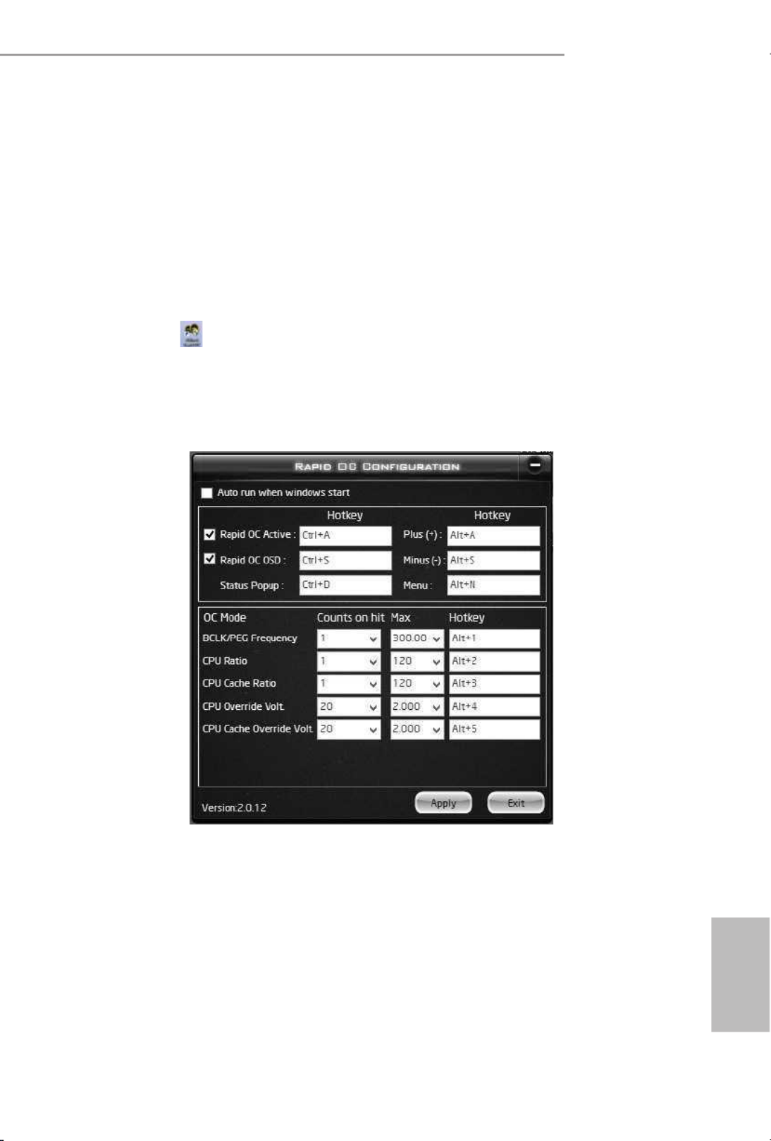
3.5 Rapid OC
ASRock Rapid OC* feature is a quick and easy way to raise and lower the CPU ratio,
BCLK frequency and CPU VCore voltage, while serious OC enthusiasts can use it to
get the highest level of overclocking performance from their system and nd their
CPU’s best margin.
*For Windows 7 and above
Step 1
Double-click on your desktop to launch the ASRock Rapid OC Conguration
soware.
Step 2
e Rapid OC Conguration screen appears.
Rapid OC Active: Enable the Rapid OC conguration function and you can press the
preset hotkeys or the onboard Rapid OC buttons, if provided, to tweak overclocking
settings.
Rapid OC OSD: e Rapid OC status window pops up instantly when pressing
Plus(+)/Minus(-) hotkeys to tweak.
Status Popup: When pressing the Status Popup hotkey, the Rapid OC status window
pops up.
Plus(+): Increase the value of the selected item

66
English
Minus(-): Decrease the value of the selected item
Menu: Press the hotkey to select among conguration options (OC mode).
On the screen, you can also adjust the hotkeys for each of the functions and how
much each press adjusts the CPU ratio, BCLK frequency and CPU VCore voltage.
Step 3
Click Apply to save the settings.

67
English
X99 OC Formula
3.6 Timing Congurator
Timing Congurator* is a fast and easy tool that provides users an overview of
abundant collection of subtle DRAM settings. You won’t even have to waste time
on entering into the UEFI or restarting the system, Timing Congurator is an
independent application that runs under Windows® OS and let you know the
current status of all conguration items immediately.
*For Windows 7 and above
*e is for reference only. e actual screen may dier by model.

69
English
X99 OC Formula
4.1.2 Navigation Keys
Use < > key or < > key to choose among the selections on the menu bar, and
use < > key or < > key to move the cursor up or down to select items, then
press <Enter> to get into the sub screen. You can also use the mouse to click your
required item.
Please check the following table for the descriptions of each navigation key.
Navigation Key(s) Description
+ / - To change option for the selected items
<Tab> Switch to next function
<PGUP> Go to the previous page
<PGDN> Go to the next page
<HOME> Go to the top of the screen
<END> Go to the bottom of the screen
<F1> To display the General Help Screen
<F7> Discard changes and exit the SETUP UTILITY
<F9> Load optimal default values for all the settings
<F10> Save changes and exit the SETUP UTILITY
<F12> Print screen
<ESC> Jump to the Exit Screen or exit the current screen
70
English
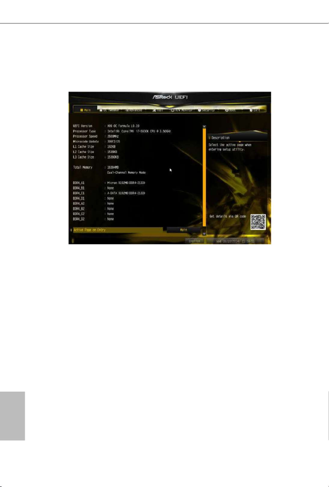
4.2 Main Screen
When you enter the UEFI SETUP UTILITY, the Main screen will appear and
display the system overview.
Active Page on Entry
Select the default page when entering the UEFI setup utility.
Full HD UEFI
When [Auto] is selected, the resolution will be set to 1920 x 1080 if the monitor
supports Full HD resolution. If the monitor does not support Full HD resolution,
then the resolution will be set to 1024 x 768. When [Disable] is selected, the
resolution will be set to 1024 x 768 directly.

71
English
X99 OC Formula
4.3 OC Tweaker Screen
In the OC Tweaker screen, you can set up overclocking features.
Load Optimized CPU OC Setting
You can use this option to load optimized CPU overclocking setting. Please note that
overclocking may cause damage to your CPU and motherboard. It should be done at your
own risk and expense.
Multi Core Enhancement
Improve the system's performance by forcing the CPU to perform the highest
frequency on all CPU cores simultaneously. Disable to reduce power consumption.
CPU Conguration
CPU Ratio
e CPU speed is determined by the CPU Ratio multiplied with the BCLK.
Increasing the CPU Ratio will increase the internal CPU clock speed without
aecting the clock speed of other components.
Because the UEFI soware is constantly being updated, the following UEFI setup screens
and descriptions are for reference purpose only, and they may not exactly match what you
see on your screen.

75
English
X99 OC Formula
RAS to RAS Delay (tRRD_L)
e number of clocks between two rows activated in dierent banks of the same
rank.
Write to Read Delay (tWTR)
e number of clocks between the last valid write operation and the next read
command to the same internal bank.
Write to Read Delay (tWTR_L)
e number of clocks between the last valid write operation and the next read command to
the same internal bank.
Read to Precharge (tRTP)
e number of clocks that are inserted between a read command to a row pre-
charge command to the same rank.
Four Activate Window (tFAW)
e time window in which four activates are allowed the same rank.
CAS Write Latency (tCWL)
Congure CAS Write Latency.
Third Timing
tREFI
Congure refresh cycles at an average periodic interval.
tCKE
Congure the period of time the DDR4 initiates a minimum of one refresh
command internally once it enters Self-Refresh mode.
tCCCD
Congure back to back CAS to CAS (i.e. READ to RAED or WRITE to WRITE)
from same rank separation parameter.
tCCCD_L
Congure back to back CAS to CAS (i.e. READ to RAED or WRITE to WRITE)
from same rank separation parameter.

79
English
X99 OC Formula
CPU Integrated VR Eciency Mode
Enable FIVR Eciency Management for power saving. Disable for better
performance and overclocking capabilities.
Voltage Conguration
Power Saving Mode
Enable Power Saving Mode to reduce power consumption.
CPU Input Voltage
Congure the voltage for the CPU.
CPU Load-Line Calibration
CPU Load-Line Calibration helps prevent CPU voltage droop when the system is
under heavy load.
DRAM Voltage
Use this to congure DRAM voltage. e default value is [Auto].
DRAM Voltage Switching Frequency
Select the DRAM voltage switching frequency.
DRAM Voltage Turn On All Phase
Enable the DRAM Voltage All Phase or set it to [Auto].
DRAM Activating Power Supply
Congure the voltage for the DRAM Activating Power Supply.
PCH PLL Voltage
Congure the chipset 1.5V voltage. Use default settings for best performance.
ICC Voltage
Congure the voltage for the ICC.
CPU I/O Voltage
Congure the voltage for the CPU IO voltage supply unit.
ME Voltage
Congure the ME voltage.

80
English
DMI PLL Voltage
Conigure the DMI PLL voltage.
PCH Voltage
Conigure the PCH voltage.

82
English
4.4.1 CPU Conguration
Intel Hyper Threading Technology
Intel Hyper reading Technology allows multiple threads to run on each core, so
that the overall performance on threaded soware is improved.
Active Processor Cores
Select the number of cores to enable in each processor package.
No-Execute Memory Protection
Processors with No-Execution Memory Protection Technology may prevent certain
classes of malicious buer overow attacks.
Hardware Prefetcher
Automatically prefetch data and code for the processor. Enable for better
performance.
Adjacent Cache Line Prefetch
Automatically prefetch the subsequent cache line while retrieving the currently
requested cache line. Enable for better performance.
Intel Virtualization Technology
Intel Virtualization Technology allows a platform to run multiple operating systems
and applications in independent partitions, so that one computer system can
function as multiple virtual systems.

83
English
X99 OC Formula
CPU Thermal Throttling
Enable CPU internal thermal control mechanisms to keep the CPU from overheat-
ing.
CPU C States Support
Enable CPU C States Support for power saving. It is recommended to keep C3, C6
and C7 all enabled for better power saving.
Package C State Support
Enable CPU, PCIe, Memory, Graphics C State Support for power saving.
CPU C3 State Support
Enable C3 sleep state for lower power consumption.
CPU C6 State Support
Enable C6 deep sleep state for lower power consumption.
Enhanced Halt State (C1E)
Enable Enhanced Halt State (C1E) for lower power consumption.

85
English
X99 OC Formula
PCI-E ASPM Support
is option enables/disables the ASPM support for all CPU downstream devices
PCH PCI-E ASPM Support
is option enables/disables the ASPM support for all PCH downstream devices
Inte(R) Ethernet Connection I218-V
Enable or disable the onboard network interface controller (Intel® I218V).
Atheros PCIE Ethernet Controller
Enable or disable the onboard network interface controller (Qualcomm® Atheros® AR8171).
Onboard HD Audio
Enable/disable onboard HD audio. Set to Auto to enable onboard HD audio and
automatically disable it when a sound card is installed.
Front Panel
Enable/disable front panel HD audio.
WAN Radio
Enable/disable the WiFi module's connectivity.
Deep Sleep
Congure deep sleep mode for power saving when the computer is shut down.
Restore on AC/Power Loss
Select the power state aer a power failure. If [Power O] is selected, the power will
remain o when the power recovers. If [Power On] is selected, the system will start
to boot up when the power recovers.
Good Night LED
By enabling Good Night LED, the Power/HDD LEDs will be switched o when the
system is on. It will also automatically switch o the Power and Keyboard LEDs
when the system enters into Standby/Hibernation mode.
Onboard Debug Port LED
Enable/disable the onboard Dr. Debug LED.

86
English
4.4.3 Storage Conguration
Hard Disk S.M.A.R.T.
S.M.A.R.T stands for Self-Monitoring, Analysis, and Reporting Technology. It is a
monitoring system for computer hard disk drives to detect and report on various
indicators of reliability.

87
English
X99 OC Formula
4.4.4 Super IO Conguration
Serial Port
Enable or disable the Serial port.
Serial Port Address
Select the address of the Serial port.
PS2 Y-Cable
Enable the PS2 Y-Cable or set this option to Auto.

88
English
4.4.5 ACPI Conguration
Suspend to RAM
Select disable for ACPI suspend type S1. It is recommended to select auto for ACPI
S3 power saving.
PS/2 Keyboard Power On
Allow the system to be waked up by a PS/2 Keyboard.
Ring-In Power On
Allow the system to be waked up by onboard COM port modem Ring-In signals.
RTC Alarm Power On
Allow the system to be waked up by the real time clock alarm. Set it to By OS to let
it be handled by your operating system.
USB Keyboard/Remote Power On
Allow the system to be waked up by an USB keyboard or remote controller.
USB Mouse Power On
Allow the system to be waked up by an USB mouse.
PCIE Devices Power On
Allow the system to be waked up by a PCIE device and enable wake on LAN.

90
English
4.4.7 Trusted Computing
Security Device Support
Enable or disable BIOS support for security device.

93
English
X99 OC Formula
Re-detect SATA Power Connection
Re-detect your SATA Power connection. It is recommended to proceed the re-detection
for any changes of your HDD conguration. You can also proceed the re-detection via the
HDD Saver application under your OS.
Easy RAID Installer
Easy RAID Installer helps you to copy the RAID driver from the support CD to
your USB storage device. Aer copying the drivers please change the SATA mode to
RAID, then you can start installing the operating system in RAID mode.
Easy Driver Installer
For users that don’t have an optical disk drive to install the drivers from our support
CD, Easy Driver Installer is a handy tool in the UEFI that installs the LAN driver
to your system via an USB storage device, then downloads and installs the other
required drivers automatically.
UEFI Tech Service
Contact ASRock Tech Service if you are having trouble with your PC. Please setup
network conguration before using UEFI Tech Service.
Instant Flash
Save UEFI les in your USB storage device and run Instant Flash to update your
UEFI.
Internet Flash - DHCP (Auto IP), Auto
ASRock Internet Flash downloads and updates the latest UEFI rmware version
from our servers for you. Please setup network conguration before using Internet
Flash.
*For BIOS backup and recovery purpose, it is recommended to plug in your USB
pen drive before using this function.
Secure Backup UEFI
Whenever one of the ROM images are outdated or corrupted, switch to the other
ash ROM and execute Secure Backup UEFI to duplicate the current working ROM
image to the secondary ash ROM.

94
English
Network Conguration
Use this to congure internet connection settings for Internet Flash.
Internet Setting
Enable or disable sound eects in the setup utility.
UEFI Download Server
Select a server to download the UEFI rmware.
Save User Default
Type a prole name and press enter to save your settings as user default.
Load User Default
Load previously saved user defaults.

95
English
X99 OC Formula
4.6 Hardware Health Event Monitoring Screen
is section allows you to monitor the status of the hardware on your system,
including the parameters of the CPU temperature, motherboard temperature, fan
speed and voltage.
CPU Fan 1 & 2 Setting
Select a fan mode for CPU Fans 1&2, or choose Customize to set 5 CPU
temperatures and assign a respective fan speed for each temperature.
Chassis Fan 1 Setting
Select a fan mode for Chassis Fan 1, or choose Customize to set 5 CPU temperatures
and assign a respective fan speed for each temperature.
Chassis Fan 1 Temp Source
Select a fan temperature source for Chassis Fan 1.
Chassis Fan 2 Setting
Select a fan mode for Chassis Fan 2, or choose Customize to set 5 CPU temperatures
and assign a respective fan speed for each temperature.
Chassis Fan 2 Temp Source
Select a fan temperature source for Chassis Fan 2.

96
English
Chassis Fan 3 Setting
Select a fan mode for Chassis Fan 3, or choose Customize to set 5 CPU temperatures
and assign a respective fan speed for each temperature.
Chassis Fan 3 Temp Source
Select a fan temperature source for Chassis Fan 3.

97
English
X99 OC Formula
4.7 Security Screen
In this section you may set or change the supervisor/user password for the system.
You may also clear the user password.
Supervisor Password
Set or change the password for the administrator account. Only the administrator
has authority to change the settings in the UEFI Setup Utility. Leave it blank and
press enter to remove the password.
User Password
Set or change the password for the user account. Users are unable to change the
settings in the UEFI Setup Utility. Leave it blank and press enter to remove the
password.
Secure Boot
Use this item to enable or disable support for Windows 8.1/8 Secure Boot.

98
English
4.8 Boot Screen
is section displays the available devices on your system for you to congure the
boot settings and the boot priority.
Fast Boot
Fast Boot minimizes your computer's boot time. In fast mode you may not boot
from an USB storage device. Ultra Fast mode is only supported by Windows 8.1/8
and the VBIOS must support UEFI GOP if you are using an external graphics card.
Please notice that Ultra Fast mode will boot so fast that the only way to enter this
UEFI Setup Utility is to Clear CMOS or run the Restart to UEFI utility in Windows.
Boot From Onboard LAN
Allow the system to be waked up by the onboard LAN.
Setup Prompt Timeout
Congure the number of seconds to wait for the setup hot key.
Bootup Num-Lock
Select whether Num Lock should be turned on or o when the system boots up.
Boot Beep
Select whether the Boot Beep should be turned on or o when the system boots up. Please
note that a buzzer is needed.

99
English
X99 OC Formula
Full Screen Logo
Enable to display the boot logo or disable to show normal POST messages.
AddOn ROM Display
Enable AddOn ROM Display to see the AddOn ROM messages or congure the
AddOn ROM if you've enabled Full Screen Logo. Disable for faster boot speed.
Boot Failure Guard
If the computer fails to boot for a number of times the system automatically restores
the default settings.
Boot Failure Guard Count
Congure the number of attempts to boot until the system automatically restores
the default settings.

100
English
CSM (Compatibility Support Module)
CSM
Enable to launch the Compatibility Support Module. Please do not disable unless
you’re running a WHCK test. If you are using Windows 8.1/8 64-bit and all of your
devices support UEFI, you may also disable CSM for faster boot speed.
Launch PXE OpROM Policy
Select UEFI only to run those that support UEFI option ROM only. Select Legacy
only to run those that support legacy option ROM only. Do not launch?
Launch Storage OpROM Policy
Select UEFI only to run those that support UEFI option ROM only. Select Legacy
only to run those that support legacy option ROM only. Do not launch?
Launch Video OpROM Policy
Select UEFI only to run those that support UEFI option ROM only. Select Legacy
only to run those that support legacy option ROM only. Do not launch?

Contact Information
If you need to contact ASRock or want to know more about ASRock, you’re welcome
to visit ASRock’s website at http://www.asrock.com; or you may contact your dealer
for further information. For technical questions, please submit a support request
form at http://www.asrock.com/support/tsd.asp
ASRock Incorporation
2F., No.37, Sec. 2, Jhongyang S. Rd., Beitou District,
Taipei City 112, Taiwan (R.O.C.)
ASRock EUROPE B.V.
Bijsterhuizen 11-11
6546 AR Nijmegen
e Netherlands
Phone: +31-24-345-44-33
Fax: +31-24-345-44-38
ASRock America, Inc.
13848 Magnolia Ave, Chino, CA91710
U.S.A.
Phone: +1-909-590-8308
Fax: +1-909-590-1026
Produktspezifikationen
| Marke: | Asrock |
| Kategorie: | Hauptplatine |
| Modell: | X99 OC FORMULA |
Brauchst du Hilfe?
Wenn Sie Hilfe mit Asrock X99 OC FORMULA benötigen, stellen Sie unten eine Frage und andere Benutzer werden Ihnen antworten
Bedienungsanleitung Hauptplatine Asrock

15 Oktober 2024
4 Oktober 2024
4 Oktober 2024
2 Oktober 2024
26 September 2024
22 September 2024
22 September 2024
17 September 2024
8 September 2024
3 September 2024
Bedienungsanleitung Hauptplatine
- Hauptplatine Asus
- Hauptplatine Gigabyte
- Hauptplatine Sharkoon
- Hauptplatine MSI
- Hauptplatine Supermicro
- Hauptplatine NZXT
- Hauptplatine ECS
- Hauptplatine EPoX
- Hauptplatine Evga
- Hauptplatine Intel
- Hauptplatine Abit
- Hauptplatine Elitegroup
- Hauptplatine Foxconn
- Hauptplatine Biostar
Neueste Bedienungsanleitung für -Kategorien-

7 Oktober 2024
5 Oktober 2024

27 September 2024
24 September 2024
19 September 2024
17 September 2024
16 September 2024
15 September 2024
13 September 2024
12 September 2024