Asrock G31M-S Bedienungsanleitung
Asrock
Hauptplatine
G31M-S
Lesen Sie kostenlos die 📖 deutsche Bedienungsanleitung für Asrock G31M-S (118 Seiten) in der Kategorie Hauptplatine. Dieser Bedienungsanleitung war für 37 Personen hilfreich und wurde von 2 Benutzern mit durchschnittlich 4.5 Sternen bewertet
Seite 1/118

ASRock G31M-GS / G31M-S Motherboard
No part of this installation guide may be reproduced, transcribed, transmitted, or trans-
lated in any language, in any form or by any means, except duplication of documen-
tation by the purchaser for backup purpose, without written consent of ASRock Inc.
Products and corporate names appearing in this guide may or may not be registered
trademarks or copyrights of their respective companies, and are used only for identifica-
tion or explanation and to the owners’ benefit, without intent to infringe.
Specifications and information contained in this guide are furnished for informational
use only and subject to change without notice, and should not be constructed as a
commitment by ASRock. ASRock assumes no responsibility for any errors or omissions
that may appear in this guide.
With respect to the contents of this guide, ASRock does not provide warranty of any kind,
either expressed or implied, including but not limited to the implied warranties or
conditions of merchantability or fitness for a particular purpose. In no event shall
ASRock, its directors, officers, employees, or agents be liable for any indirect, special,
incidental, or consequential damages (including damages for loss of profits, loss of
business, loss of data, interruption of business and the like), even if ASRock has been
advised of the possibility of such damages arising from any defect or error in the guide
or product.
This device complies with Part 15 of the FCC Rules. Operation is subject to the
following two conditions:
(1) this device may not cause harmful interference, and
(2) this device must accept any interference received, including interference that
may cause undesired operation.
Published May 2009
Copyright©2009 ASRock INC. All rights reserved.
CALIFORNIA, USA ONLY
The Lithium battery adopted on this motherboard contains Perchlorate, a toxic
substance controlled in Perchlorate Best Management Practices (BMP) regulations
passed by the California Legislature. When you discard the Lithium battery in
California, USA, please follow the related regulations in advance.
“Perchlorate Material-special handling may apply, see
www.dtsc.ca.gov/hazardouswaste/perchlorate”
ASRock Website: http://www.asrock.com
ASRock G31M-GS / G31M-S Motherboard
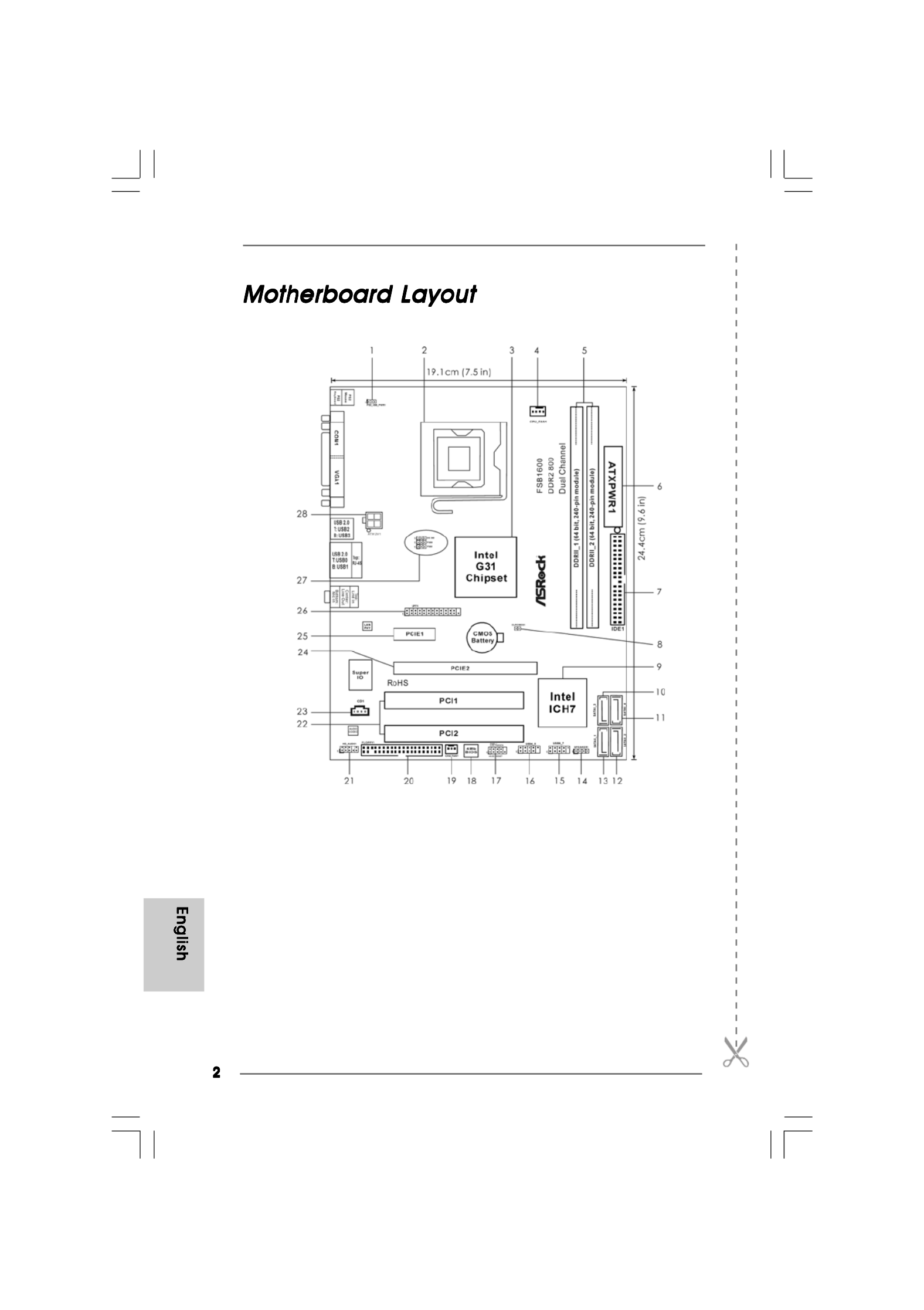
1 PS2_USB_PWR1 Jumper 15 USB 2.0 Header (USB6_7, Blue)
2 775-Pin CPU Socket 16 USB 2.0 Header (USB4_5, Blue)
3 North Bridge Controller 17 System Panel Header (PANEL1, Orange)
4 CPU Fan Connector (CPU_FAN1) 18 BIOS SPI Chip
5 2 x 240-pin DDR2 DIMM Slots 19 Chassis Fan Connector (CHA_FAN1)
(Dual Channel: DDRII_1, DDRII_2; Yellow) 20 Floppy Connector (FLOPPY1)
6 ATX Power Connector (ATXPWR1) 21 Front Panel Audio Header
7 IDE1 Connector (IDE1, Blue) (HD_AUDIO1, Lime)
8 Clear CMOS Jumper (CLRCMOS1) 22 PCI Slots (PCI1- 2)
9 South Bridge Controller 23 Internal Audio Connector: CD1 (Black)
10 Third SATAII Connector (SATAII_3; Orange) 24 PCI Express x16 Slot (PCIE2)
11 Fourth SATAII Connector (SATAII_4; Orange) 25 PCI Express p2-x1 Slot (PCIE1)
12 Secondary SATAII Connector (SATAII_2; Red) 26 Print Port Header (LPT1, Purple)
13 Primary SATAII Connector (SATAII_1; Red) 27 OC 800 / FSB0 / FSB1 Jumper
14 Chassis Speaker Header (SPEAKER 1, 28 ATX 12V Connector (ATX12V1)
Purple)

ASRock G31M-GS / G31M-S Motherboard
1 PS/2 Mouse Port (Green) 6 Microphone (Pink)
2 USB 2.0 Ports (USB23) 7 USB 2.0 Ports (USB01)
3 RJ-45 Port 8 VGA Port
4 Line In (Light Blue) 9 COM Port
5 Line Out (Lime) 10 PS/2 Keyboard Port (Purple)
* To enable Multi-Streaming function, you need to connect a front panel audio cable to the front
panel audio header. Please refer to below steps for the software setting of Multi-Streaming.
For Windows
® XP:
After restarting your computer, you will find “Mixer” tool on your system. Please select “Mixer
ToolBox” , click “Enable playback multi-streaming”, and click “ok”. Choose “2CH” or
“4CH” and then you are allowed to select “Realtek HDA Primary output” to use Rear Speaker
and Front Speaker, or select “Realtek HDA Audio 2nd output” to use front panel audio. Then
reboot your system.
For Windows® Vista
TM
:
After restarting your computer, please double-click “Realtek HD Audio Manager” on the
system tray. Set “Speaker Configuration” to “Quadraphonic” or “Stereo”. Click “Device
advanced settings”, choose “Make front and rear output devices playbacks two different audio
streams simultaneously”, and click “ok”. Then reboot your system.

ASRock G31M-GS / G31M-S Motherboard
Thank you for purchasing ASRock G31M-GS / G31M-S motherboard, a reliable mother-
board produced under ASRock’s consistently stringent quality control. It delivers excel-
lent performance with robust design conforming to ASRock’s commitment to quality and
endurance.
This Quick Installation Guide contains introduction of the motherboard and step-by-
step installation guide. More detailed information of the motherboard can be found in
the user manual presented in the Support CD.
Because the motherboard specifications and the BIOS software might
be updated, the content of this manual will be subject to change without
notice. In case any modifications of this manual occur, the updated
version will be available on ASRock website without further notice. You
may find the latest VGA cards and CPU support lists on ASRock website
as well. ASRock website http://www.asrock.com
If you require technical support related to this motherboard, please visit
our website for specific information about the model you are using.
www.asrock.com/support/index.asp
ASRock G31M-GS / G31M-S Motherboard
(Micro ATX Form Factor: 9.6-in x 7.5-in, 24.4 cm x 19.1 cm)
ASRock G31M-GS / G31M-S Quick Installation Guide
ASRock G31M-GS / G31M-S Support CD
One 80-conductor Ultra ATA 66/100 IDE Ribbon Cable (Optional)
One Serial ATA (SATA) Data Cable (Optional)
One Serial ATA (SATA) HDD Power Cable (Optional)
One I/O Panel Shield

ASRock G31M-GS / G31M-S Motherboard
Connector - 4 x SATAII 3.0 Gb/s connectors (No Support for RAID and
“Hot Plug” functions) (see CAUTION 8)
- 1 x ATA100 IDE connector (supports 2 x IDE devices)
- 1 x Floppy connector
- 1 x Print port header
- CPU/Chassis FAN connector
- 24 pin ATX power connector
- 4 pin 12V power connector
- CD in header
- Front panel audio connector
- 2 x USB 2.0 headers (support 4 USB 2.0 ports)
(see CAUTION 9)
BIOS Feature - 4Mb AMI BIOS
- AMI Legal BIOS
- Supports “Plug and Play”
- ACPI 1.1 Compliance Wake Up Events
- Supports jumperfree
- AMBIOS 2.3.1 Support
- Supports Smart BIOS
Support CD - Drivers, Utilities, AntiVirus Software (Trial Version)
Unique Feature - ASRock OC Tuner (see CAUTION 10)
- Intelligent Energy Saver (see CAUTION 11)
- Hybrid Booster:
- CPU Frequency Stepless Control (see CAUTION 12)
- ASRock U-COP (see CAUTION 13)
- Boot Failure Guard (B.F.G.)
Hardware - CPU Temperature Sensing
Monitor - Chassis Temperature Sensing
- CPU Fan Tachometer
- Chassis Fan Tachometer
- CPU Quiet Fan
- Voltage Monitoring: +12V, +5V, +3.3V, Vcore
OS - Microsoft® Windows® 2000 / XP / XP 64-bit / VistaTM /
VistaTM 64-bit compliant
Certifications - FCC, CE
* For detailed product information, please visit our website: http://www.asrock.com

ASRock G31M-GS / G31M-S Motherboard
11. Featuring an advanced proprietary hardware and software design,
Intelligent Energy Saver is a revolutionary technology that delivers
unparalleled power savings. In other words, it is able to provide excep-
tional power saving and improve power efficiency without sacrificing
computing performance. Please visit our website for the operation pro-
cedures of Intelligent Energy Saver.
ASRock website: http://www.asrock.com
12. Although this motherboard offers stepless control, it is not recom-
mended to perform over-clocking. Frequencies other than the recom-
mended CPU bus frequencies may cause the instability of the system
or damage the CPU.
13. While CPU overheat is detected, the system will automatically shutdown.
Before you resume the system, please check if the CPU fan on the
motherboard functions properly and unplug the power cord, then plug it
back again. To improve heat dissipation, remember to spray thermal
grease between the CPU and the heatsink when you install the PC
system.

ASRock G31M-GS / G31M-S Motherboard
Take note of the following precautions before you install mother-
board components or change any motherboard settings.
1. Unplug the power cord from the wall socket before touching any
component. Failure to do so may cause severe damage to the
motherboard, peripherals, and/or components.
2. To avoid damaging the motherboard components due to static
electricity, NEVER place your motherboard directly on the carpet
or the like. Also remember to use a grounded wrist strap or touch
a safety grounded object before you handle components.
3. Hold components by the edges and do not touch the ICs.
4. Whenever you uninstall any component, place it on a grounded
antstatic pad or in the bag that comes with the component.
5. When placing screws into the screw holes to secure the
motherboard to the chassis, please do not over-tighten the
screws! Doing so may damage the motherboard.
For the installation of Intel 775-LAND CPU,
please follow the steps below.
Before you insert the 775-LAND CPU into the socket, please check if
the CPU surface is unclean or if there is any bent pin on the socket.
Do not force to insert the CPU into the socket if above situation is
found. Otherwise, the CPU will be seriously damaged.
775-Pin Socket Overview
ASRock G31M-GS / G31M-S Motherboard
1. It is recommended to use the cap tab to handle and avoid kicking
off the PnP cap.
2. This cap must be placed if returning the motherboard for after
service.
Step 4. Close the socket:
Step 4-1. Rotate the load plate onto the IHS.
Step 4-2. While pressing down lightly on load
plate, engage the load lever.
Step 4-3. Secure load lever with load plate tab
under retention tab of load lever.
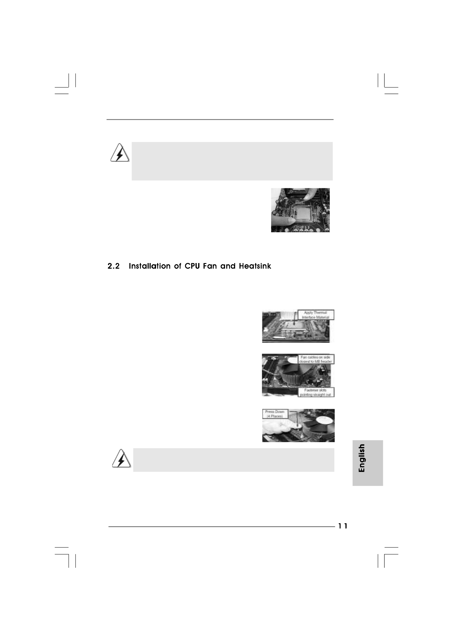
For proper installation, please kindly refer to the instruction manuals of your CPU fan
and heatsink.
Below is an example to illustrate the installation of the heatsink for 775-LAND CPU.
Step 1. Apply thermal interface material onto center
of IHS on the socket surface.
Step 2. Place the heatsink onto the socket. Ensure
fan cables are oriented on side closest to the
CPU fan connector on the motherboard
(CPU_FAN1, see page 2, No. 4).
Step 3. Align fasteners with the motherboard
throughholes.
Step 4. Rotate the fastener clockwise, then press
down on fastener caps with thumb to install
and lock. Repeat with remaining fasteners.
If you press down the fasteners without rotating them clockwise,
the heatsink cannot be secured on the motherboard.
Step 5. Connect fan header with the CPU fan
connector on the motherboard.
Step 6. Secure excess cable with tie-wrap to ensure
cable does not interfere with fan operation or
contact other components.

ASRock G31M-GS / G31M-S Motherboard
G31M-GS / G31M-S motherboard provides two 240-pin DDR2 (Double Data Rate 2)
DIMM slots, and supports Dual Channel Memory Technology. For dual channel
configuration, you always need to install two identical (the same brand, speed, size and
chip-type) memory modules in the DDR2 DIMM slots to activate Dual Channel Memory
Technology. Otherwise, it will operate at single channel mode.
1. It is not allowed to install a DDR memory module into DDR2 slot;
otherwise, this motherboard and DIMM may be damaged.
2. If you install only one memory module or two non-identical memory
modules, it is unable to activate the Dual Channel Memory Technology.
Please make sure to disconnect power supply before adding or
removing DIMMs or the system components.
Step 1. Unlock a DIMM slot by pressing the retaining clips outward.
Step 2. Align a DIMM on the slot such that the notch on the DIMM matches the break
on the slot.
The DIMM only fits in one correct orientation. It will cause permanent
damage to the motherboard and the DIMM if you force the DIMM into the
slot at incorrect orientation.
Step 3. Firmly insert the DIMM into the slot until the retaining clips at both ends fully
snap back in place and the DIMM is properly seated.
ASRock G31M-GS / G31M-S Motherboard
There are 2 PCI slots and 2 PCI Express slots on this motherboard.
PCI slots: PCI slots are used to install expansion cards that have the 32-bit PCI
interface.
PCIE slots:
PCIE1 (PCIE p13-x1 slot) is used for PCI Express cards with p13-x1 lane width
cards, such as Gigabit LAN card, SATA2 card, etc.
PCIE2 (PCIE x16 slot) is used for PCI Express cards with x16 lane
width graphics cards.
If you install the add-on PCI Express VGA card to PCIE2 (PCIE x16 slot),
the onboard VGA will be disabled. If you install the add-on PCI Express
VGA card to PCIE2 (PCIE x16 slot) and adjust the “Internal Graphics
Mode Select” BIOS option to [Enabled], the onboard VGA will be enabled,
and the primary screen will be onboard VGA.
Step 1. Before installing the expansion card, please make sure that the power supply
is switched off or the power cord is unplugged. Please read the documentation
of the expansion card and make necessary hardware
settings for the card before you start the installation.
Step 2. Remove the bracket facing the slot that you intend to use. Keep the screws
for later use.
Step 3. Align the card connector with the slot and press firmly until the card is com-
pletely seated on the slot.
Step 4. Fasten the card to the chassis with screws.

ASRock G31M-GS / G31M-S Motherboard
The illustration shows how jumpers are
setup. When the jumper cap is placed on
pins, the jumper is “Short”. If no jumper cap
is placed on pins, the jumper is “Open”. The
illustration shows a 3-pin jumper whose pin1
and pin2 are “Short” when jumper cap is
placed on these 2 pins.
Jumper Setting Description
PS2_USB_PWR1 Short pin2, pin3 to enable
(see p.2 No. 1) +5VSB (standby) for PS/2
or USB wake up events.
Note: To select +5VSB, it requires 2 Amp and higher standby current provided by
power supply.
Clear CMOS
(CLRCMOS1, 2-pin jumper)
(see p.2 No. 8)
Note: CLRCMOS1 allows you to clear the data in CMOS. The data in CMOS includes
system setup information such as system password, date, time, and system
setup parameters. To clear and reset the system parameters to default setup,
please turn off the computer and unplug the power cord from the power
supply. After waiting for 15 seconds, use a jumper cap to short 2 pins on
CLRCMOS1 for 5 seconds.
2-pin jumper
Short Open

ASRock G31M-GS / G31M-S Motherboard
OC 800 / FSB0 / FSB1 Jumper
(OC 800 / FSB0 / FSB1, 3-pin jumper,
see p.2 No. 27)
Note: If you want to overclock the FSB800-CPU (e.g. Cel400, E1000, E2000, E4000,
E5000, E6000 series CPU) to FSB1066 on this motherboard, you need to adjust
the jumpers. Please short pin2, pin3 for OC800 jumper. Otherwise, the CPU may
not work properly on this motherboard. Please refer to below jumper settings.
Default

ASRock G31M-GS / G31M-S Motherboard
System Panel Header This header accommodates
(9-pin PANEL1) several system front panel
(see p.2 No. 17) functions.
Chassis Speaker Header Please connect the chassis
(4-pin SPEAKER 1) speaker to this header.
(see p.2 No. 14)
Chassis Fan Connector Please connect a chassis fan
(3-pin CHA_FAN1) cable to this connector and
(see p.2 No. 19) match the black wire to the
ground pin.
CPU Fan Connector Please connect a CPU fan cable
(4-pin CPU_FAN1) to this connector and match
(see p.2 No. 4) the black wire to the ground pin.
D. MIC_RET and OUT_RET are for HD audio panel only. You don’t
need to connect them for AC’97 audio panel.
E. Enter BIOS Setup Utility. Enter Advanced Settings, and then select
Chipset Configuration. Set the Front Panel Control option from
[Auto] to [Enabled].
F. Enter Windows system. Click the icon on the lower right hand
taskbar to enter Realtek HD Audio Manager.
For Windows® 2000 / XP / XP 64-bit OS:
Click “Audio I/O”, select “Connector Settings” , choose
“Disable front panel jack detection”, and save the change by
clicking “OK”.
For Windows
® VistaTM / VistaTM 64-bit OS:
Click the right-top “Folder” icon , choose “Disable front
panel jack detection”, and save the change by clicking “OK”.
G. To activate the front mic.
For Windows® 2000 / XP / XP 64-bit OS:
Please select “Front Mic” as default record device.
If you want to hear your voice through front mic, please deselect "Mute"
icon in “Front Mic” of “Playback” portion.
For Windows
® VistaTM / VistaTM 64-bit OS:
Go to the "Front Mic" Tab in the Realtek Control panel.
Click "Set Default Device" to make the Front Mic as the default record
device.
4 3 2 1

ASRock G31M-GS / G31M-S Motherboard
20-Pin ATX Power Supply Installation
Though this motherboard provides 4-Pin CPU fan (Quiet Fan) support, the 3-Pin
CPU fan still can work successfully even without the fan speed control function.
If you plan to connect the 3-Pin CPU fan to the CPU fan connector on this
motherboard, please connect it to Pin 1-3.
3-Pin Fan Installation
Pin 1-3 Connected
ATX 12V Connector Please note that it is necessary
(4-pin ATX12V1) to connect a power supply with
(see p.2 No. 28) ATX 12V plug to this connector
so that it can provides sufficient
power. Failing to do so will cause
the failure to power up.
ATX Power Connector Please connect an ATX power
(24-pin ATXPWR1) supply to this connector.
(see p.2 No. 6)
Though this motherboard provides 24-pin ATX power connector,
it can still work if you adopt a traditional 20-pin ATX power supply.
To use the 20-pin ATX power supply, please plug your power
supply along with Pin 1 and Pin 13.
12
1
24
13
12
1
24
13

ASRock G31M-GS / G31M-S Motherboard
Please refer to the warning on page 7 for the possible overclocking risk
before you apply Untied Overclocking Technology.
This motherboard adopts Intel
® ICH7 south bridge chipset that supports Serial ATA
(SATA) / Serial ATAII (SATAII) hard disks. You may install SATA / SATAII hard disks on
this motherboard for internal storage devices. This section will guide you to install the
SATA / SATAII hard disks.
STEP 1: Install the SATA / SATAII hard disks into the drive bays of your chassis.
STEP 2: Connect the SATA power cable to the SATA / SATAII hard disk.
STEP 3: Connect one end of the SATA data cable to the motherboard’s SATAII
connector.
STEP 4: Connect the other end of the SATA data cable to the SATA / SATAII hard
disk.
To install the drivers to your system, please insert the support CD to your optical drive
first. Then, the drivers compatible to your system can be auto-detected and listed on
the support CD driver page. Please follow the order from up to bottom side to install
those required drivers. Therefore, the drivers you install can work properly.
This motherboard supports Untied Overclocking Technology, which means during
overclocking, FSB enjoys better margin due to fixed PCI / PCIE buses. Before you
enable Untied Overclocking function, please enter “Overclock Mode” option of BIOS setup
to set the selection from [Auto] to [CPU, PCIE, Async.]. Therefore, CPU FSB is untied
during overclocking, but PCI / PCIE buses are in the fixed mode so that FSB can operate
under a more stable overclocking environment.

ASRock G31M-GS / G31M-S Motherboard
Plattform - Micro ATX-Formfaktor: 24.4 cm x 19.1 cm; 9.6 Zoll x 7.5 Zoll
CPU - LGA 775 für Intel® CoreTM 2 Extreme / CoreTM 2 Quad / CoreTM
2 Duo / Pentium® Dual Core / Celeron
® Dual Core / Celeron®
unterstützt Penryn Quad Core Yorkfield und Dual Core
Wolfdale Prozessoren
- Kompatibilität mit FSB1600/1333/1066/800 MHz
(siehe VORSICHT 1)
- Unterstützt Hyper-Threading-Technologie
(siehe VORSICHT 2)
- Unterstützt Untied-Übertaktungstechnologie
(siehe VORSICHT 3)
- Unterstützt EM64T-CPU
Chipsatz - Northbridge: Intel®
G31
- Southbridge: Intel®
ICH7
Speicher - Unterstützung von Dual-Kanal-DDR2-Speichertechnologie
(siehe VORSICHT 4)
- 2 x Steckplätze für DDR2
- Unterstützt DDR2 800/667 non-ECC, ungepufferter Speicher
(siehe VORSICHT 5)
- Max. Kapazität des Systemspeichers: 8GB
(siehe VORSICHT 6)
Erweiterungs- - 1 x PCI Express x16-Steckplätze
steckplätze - 1 x PCI Express x1-Steckplätze
- 2 x PCI -Steckplätze
Onboard-VGA - Intel® Graphics Media Accelerator 3100
- Pixel Shader 2.0, DX9.0 VGA
- Maximal gemeinsam genutzter Speicher 384MB
(siehe VORSICHT 7)
Audio - 5.1 CH Windows
® VistaTM Premium Level HD Audio
(ALC662 Audio Codec)
LAN - G31M-GS
Realtek PCIE x 1 Gigabit LAN RTL8111DL,
speed 10/100/1000 Mb/s
- G31M-S
Realtek PCIE p23-x1 LAN 8102EL, speed 10/100 Mb/s
- Unterstützt Wake-On-LAN
E/A-Anschlüsse I/O Panel
an der - 1 x PS/2 Mouse Port
Rückseite - 1 x PS/2 Keyboard Port
ASRock G31M-GS / G31M-S Motherboard
- 1 x Serieller port: COM 1
- 1 x VGA Port
- 4 x Ready-to-Use USB 2.0 Ports
- 1 x RJ-45 Port
- Audioanschlüsse: Line In / Line Out / Mikrofon
Anschlüsse - 4 x SATAII-Anschlüsse, unterstützt bis 3.0 Gb/s
Datenübertragungsrate (Unterstützt keine “RAID”- und “Hot-
Plug”-Funktionen) (siehe VORSICHT 8)
- 1 x ATA100 IDE-Anschlüsse (Unterstützt bis 2 IDE-Geräte)
- 1 x FDD-Anschlüsse
- 1 x Druckerport-Anschlussleiste
- CPU/Gehäuse-Lüfteranschluss
- 24-pin ATX-Netz-Header
- 4-pin anschluss für 12V-ATX-Netzteil
- Interne Audio-Anschlüsse
- Anschluss für Audio auf der Gehäusevorderseite
- 2 x USB 2.0 Buchse (unterstützt 4 USB 2.0 Ports)
(siehe VORSICHT 9)
BIOS - 4Mb AMI BIOS
- AMI legal BIOS mit Unterstützung für “Plug and Play”
- ACPI 1.1-Weckfunktionen
- JumperFree-Modus
- SMBIOS 2.3.1
- Unterstützt Smart BIOS
Support-CD - Treiber, Dienstprogramme, Antivirussoftware
(Probeversion)
Einzigartige - ASRock OC Tuner (siehe VORSICHT 10)
Eigenschaft - Intelligent Energy Saver (Intelligente Energiesparfunktion)
(siehe VORSICHT 11)
- Hybrid Booster:
- Schrittloser CPU-Frequenz-Kontrolle
(siehe VORSICHT 12)
- ASRock U-COP (siehe VORSICHT 13)
- Boot Failure Guard (B.F.G. – Systemstartfehlerschutz)
Hardware Monitor - Überwachung der CPU-Temperatur
- Motherboardtemperaturerkennung
- Drehzahlmessung für CPU-Lüfter
- Drehzahlmessung für Gehäuselüfter
- CPU-Lüftergeräuschdämpfung
- Spannungsüberwachung: +12V, +5V, +3.3V, Vcore
Betriebssysteme - Unterstützt Microsoft
® Windows® 2000 / XP / XP 64-Bit /
VistaTM / VistaTM 64-Bit
Zertifizierungen - FCC, CE

ASRock G31M-GS / G31M-S Motherboard
Par défaut
Cavalier OC 800 / FSB0 / FSB1
(OC 800 / FSB0 / FSB1, cavalier à 3 broches,
voir p.2 N° 27)
Note: Si vous voulez overclocker le CPU FSB800 (par ex les gammes de CPU
Cel400, E1000, E2000, E4000, E5000, E6000) en FSB1066 sur cette carte
mère, il vous faut régler les cavaliers. Veuillez mettre en contact les bornes 2 et
3 pour le cavalier OC 800. Sinon le CPU peut ne pas fonctionner correctement
sur cette carte mère. Veuillez vous référer aux réglages des cavaliers ci-
dessous.

ASRock G31M-GS / G31M-S Motherboard
Predefinito
Jumper OC 800 / FSB0 / FSB1
(OC 800 / FSB0 / FSB1, jumper a 3 pin,
vedere p.2 N. 27)
Nota: Se – su questa scheda madre – si vuole eseguire l’overclocking della CPU da
FSB800 (e.g. CPU serie Cel400, E1000, E2000, E4000, E5000, E6000) a
FSB1066, è necessario regolare i jumper. Ridurre pin 2, pin 3 per jumper OC
800. Diversamente – su questa scheda madre – la CPU potrebbe non
funzionare in modo appropriato. Fare riferimento a quanto segue per
l’impostazione dei jumper.
Produktspezifikationen
| Marke: | Asrock |
| Kategorie: | Hauptplatine |
| Modell: | G31M-S |
| Prozessorhersteller: | Intel |
| Breite: | 244 mm |
| Tiefe: | 191 mm |
| Energiequelle: | ATX |
| Kopfhörerausgänge: | 1 |
| Anzahl USB 2.0 Anschlüsse: | 4 |
| Zertifizierung: | FCC, CE |
| Anzahl Ethernet-LAN-Anschlüsse (RJ-45): | 1 |
| Audio Kanäle: | 5.1 Kanäle |
| Mikrofon-Eingang: | Ja |
| Kompatible Betriebssysteme: | Microsoft Windows 2000 / XP / XP 64-bit / Vista / Vista 64-bit |
| Prozessorsockel: | LGA 775 (Socket T) |
| Anzahl VGA (D-Sub) Anschlüsse: | 1 |
| Motherboardformfaktor: | micro ATX |
| Audio-Chip: | Realtek ALC662 |
| Anzahl der Speichersteckplätze: | 2 |
| Ohne ECC: | Ja |
| RAM-Speicher maximal: | 8 GB |
| Maximaler Grafikkartenspeicher: | 384 MB |
| Anzahl PS/2 Anschlüsse: | 2 |
| ATX Stromstecker (24-pol.): | Ja |
| Anzahl USB 2.0 Schnittstellen: | 2 |
| CPU Ventilatorstecker: | Ja |
| Front Panel Audiostecker: | Ja |
| BIOS-Speichergröße: | 32 Mbit |
| BIOS-Typ: | AMI |
| Zahl der parallelen ATA Stecker: | 1 |
| Anzahl serielle Anschlüsse: | 1 |
| Power Fan Connector: | Nein |
| PCI-Express x16-Slots: | 1 |
| PCI-Express x1-Slots: | 1 |
| PCI-Slots: | 2 |
| Netzwerkfunktionen: | PCIE x1 LAN |
| SATA Anschlüsse: | 4 |
| CD/AUX Audio-Eingang: | Ja |
| Diskettenlaufwerkstecker: | Ja |
| (2.) Controller-Schnittstelle: | ATA100 |
| Redundante Controller: | SATAII |
| Grafikcontroller: | Intel Graphics Media Accelerator 3100 |
Brauchst du Hilfe?
Wenn Sie Hilfe mit Asrock G31M-S benötigen, stellen Sie unten eine Frage und andere Benutzer werden Ihnen antworten
Bedienungsanleitung Hauptplatine Asrock

15 Oktober 2024
4 Oktober 2024
4 Oktober 2024
2 Oktober 2024
26 September 2024
22 September 2024
22 September 2024
17 September 2024
8 September 2024
3 September 2024
Bedienungsanleitung Hauptplatine
- Hauptplatine Asus
- Hauptplatine Gigabyte
- Hauptplatine Sharkoon
- Hauptplatine MSI
- Hauptplatine Supermicro
- Hauptplatine NZXT
- Hauptplatine ECS
- Hauptplatine EPoX
- Hauptplatine Evga
- Hauptplatine Intel
- Hauptplatine Abit
- Hauptplatine Elitegroup
- Hauptplatine Foxconn
- Hauptplatine Biostar
Neueste Bedienungsanleitung für -Kategorien-

7 Oktober 2024
5 Oktober 2024

27 September 2024
24 September 2024
19 September 2024
17 September 2024
16 September 2024
15 September 2024
13 September 2024
12 September 2024